Analog Input
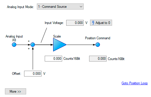
If the drive command source is set to analog, then the analog input to the drive supplies the current or velocity command to the control loops of the drive.The default analog input screen displays a summary block diagram of the analog input. You can adjust the analog input settings from this view as follows:
| Button or Dialog Box | Description | Parameter |
|---|---|---|
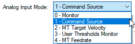
| Analog Input Mode |
This parameter assigns a functionality to the voltage measured on the analog input pin.
|
AIN.MODE |
| Adjust to 0 | Sets the offset, AIN.OFFSET, to the opposite value of the analog input, so that the resulting voltage, AIN.VALUE, equals 0. | AIN.ZERO |
|
Offset |
The offset adds a bias to the analog input command. This offset is commonly used to remove any biases that may be present on the analog input signal. |
|
|
Input Voltage |
The value of the analog input after the offset, and low pass filters. |
|
|
Scale |
If the opmode is current mode, then this value is the amount of current that will be commanded for each volt on the analog input. If the opmode is velocity mode, then this value is the velocity that will be commanded for each volt on the analog input. Note: Scaling in KAS is 80% of that in AKD. In AKD 10 V = 32767 while in KAS 10 V = 26126 |
AIN.ISCALE , AIN.VSCALE , or AIN.PSCALE
|
|
Torque Command |
The current, position, or velocity command that is sent to the control loops. |
Click the More button to access a detailed view of the analog input. You can adjust additional analog input settings from this view as follows:
| Button or Dialog Box | Description | Parameter |
|---|---|---|
|
Low Pass Filter |
The break point frequency for the low pass filter.
|
|
|
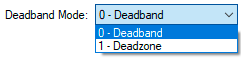
Deadband Mode |
Selects the threshold for the deadband. This parameter is commonly used to reduce noise while the drive is stationary.
|
Both analog input views provide a link to the encoder emulation output setup; see Encoder Emulation for more details on this feature.
Related Parameters