Electronic Gearing
Overview
Electronic gearing is the act of sending a digital pulse position command to the AKD drive. The X9 connector is used for controlling the drive through an A/B type signal, pulse and direction (also called step and direction), or CW/CCW command. A common application for electronic gearing is using servos with a stepper controller or daisy chaining multiple AKD drives from one master drive as slave drives.
To command an AKD using electronic gearing, the command source (DRV.CMDSOURCE) must be set to 2 - Electronic Gearing and the opmode (DRV.OPMODE) must be set to 2 - Position Mode.

The input modes of the X9 connector are used to set up the AKD for electronic gearing.
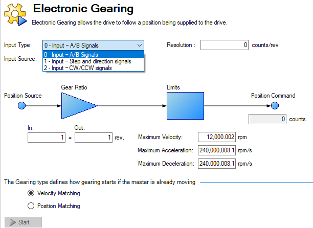
Resolution is the post-quadrature value of the counts/revolution of the input. Additionally, a gear ratio can be applied to affect the output ratio of the motor.
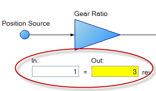
The position command (DRV.HANDWHEEL) reads the EEO value, where 4,294,967,296 is a full revolution of the input, then the value rolls over. Gear ratio does not affect the EEO value. If the output is set to 3 output revolutions per input revolution, there are 4,294,967,296 counts per 3 revolutions of the motor.
Limits
Electronic Gearing has independent limits, as shown below:
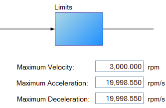
These limits (GEAR.ACCMAX, GEAR.DECMAX, GEAR.VELMAX) are applied only during gearing mode and the units are consistent with speed and acceleration of the output motor. All other limits in the drive are active along with gearing limits.
-
-
Since the master determines the trajectory profile of the slave, it is not common to need to set GEAR limits to change the profile from the master. Erratic motion may result since they can clamp the servo command. This includes, when using a Pul/Dir type signal, slave motion continuing even after the master signal is removed from connector X9 on the slave AKD drive. If you are experiencing problems, first increase these limits to their maximums.
If the master is already moving when entering electronic gearing mode, velocity or position can be matched (GEAR.MODE):
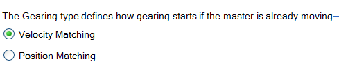
In Velocity Matching, the motor will ramp up to the same velocity with no concern over lost steps during the acceleration period.
In Position Matching, the motor will match the position command from the switchover point by speeding up to recover the lost steps during the acceleration period.
Velocity Feedforward Setting
In some gearing applications, VL.KVFF must be reduced or set to 0 to reduce audible noise.
Determining Maximum Cable Length
When you use an external incremental encoder as an input to X9, you must determine the maximum allowable cable length.
-
-
This information is only applicable when using an external encoder as either a secondary feedback input or a gearing command (DRV.EMUEMODE3). Not applicable for any other X9 mode or when using two AKDs in a master/slave system.
The X9 port has a 5V output used to supply power to an external incremental encoder.
The maximum cable length depends on the current draw of the external encoder and the cable type connecting the X9 port. The following example can be used as a guide to calculate the maximum cable length for your application.
X9 port characteristics:
Nominal Supply Voltage:5 V
Tolerance: 5%
Minimum Supply Voltage: 4.75 V
Maximum current: 0.25 A
Permitted wire gauge: 20-28 AWB (Typical for D9 connector)
Sample Application Hardware:
Example external encoder: Hengstler RI-36H (RS-422 encoder) used with X9 port.
Encoder Nominal Supply Voltage: 5V (+/- 10%)
Minimum Supply Voltage: 4.5 V calculated based on tolerance above
Maximum required encoder supply current: 50 mA
Example cable:
Lapp Li2YCY - 24AWG (0.22 mm^2)
Loop resistance: 0.186 Ohms/m
Sample Calculations:
Maximum Permissible voltage cable drop = 0.25 V
= (Minimum Supply Voltage from AKD) 4.75 V – (Minimum supply voltage of RI-36H encoder) 4.5V
Maximum permissible resistance of cable run to X9 = 5 Ohms
= (Max voltage cable drop) 0.25V ÷ (Maximum encoder current) 0.05A
Maximum permissible cable length for example application = 26.9 m
= (Max cable resistance) 5 Ohms ÷ 0.186 Ohms/m
Related Parameters