The foldback feature in the AKD protects both the motor and the drive from overheating. Two current foldback algorithms run in parallel in the drive: the drive foldback algorithm and the motor foldback algorithm. Each algorithm uses different sets of parameters. Each algorithm has its own foldback current limit, IL.DIFOLD (drive foldback) and IL.MIFOLD (motor foldback). The overall foldback current limit is the minimum of the two at any given moment.
IL.IFOLD = min (IL.DIFOLD, IL.MIFOLD).
Foldback is not the same as current limits. Instantaneous current limits for the drive are set by the positive peak current (IL.LIMITP) and negative peak current (IL.LIMITN) in the Limits view in WorkBench. The foldback algorithms may reduce the current output to the motor in spite of the current limit settings.
Drive Foldback
The drive foldback algorithm monitors current feedback; since this is a monitoring function, the drive foldback parameters are not user configurable. If the current feedback exceeds the continuous current rating of the drive (DRV.ICONT), then the algorithm decreases the current to the DRV.ICONT level. For example, under a step command input condition, the foldback algorithm allows maximum peak current (DRV.IPEAK) output from the drive for a short period of time (up to IL.DFOLDD time), after which the drive begins an exponential foldback (with time constant of IL.DFOLDT) of the current to the drive’s continuous current.
It takes a few seconds for the exponential decay to drop from the drive’s peak current to its continuous level. A recovery time, when the feedback current is below DRV.ICONT level, is required to allow current above DRV.ICONT level again. A recovery time of IL.DFOLDR with 0 current allows the drive to apply DRV.IPEAK current for IL.DFOLDD time.
-
- For AKD-N, the drive foldback is in recovery mode after boot or power cycle. This means drive peak current is reduced until the foldback algorithm has fully recovered.
Setting up motor foldback
Motor foldback is set up automatically when using a plug and play motor or when a particular motor is selected from the WorkBench database.
If you are using a custom motor, use the Motor view in WorkBench to set custom values needed for foldback configuration. The parameter entries required for the drive to apply motor foldback protection properly are coil thermal constant (MOTOR.CTFO), peak current of the motor (MOTOR.IPEAK), and continuous current of the motor (MOTOR.ICONT). These values are used to setup the algorithm for motor foldback.
Setting Fault and Warning Levels
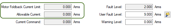
The Motor Foldback Current Limit and Allowable Limit fields show status variables that are constantly updated by the foldback algorithm. As current is applied above the drive or motor continuous rating, the capacity for the application of peak current starts to decrease. The motor foldback current limit and overall current limit are actively decreased. If the move profile requires less than continuous current rating for a period of time, the Motor Foldback Current Limit and Allowable Limit begin to increase until they reach maximum foldback capacity once again.
When Motor Foldback Current Limit or Allowable Limit < Warning Level, an n524 status warning is triggered. When Motor Foldback Current Limit or Allowable Limit < Fault Level, an F524 fault is triggered and the drive power stage is disabled. The load then coasts to a stop.
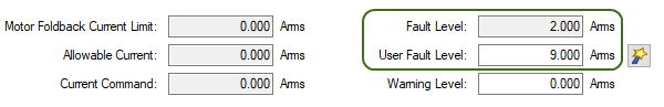
On the Foldback view, setting the Warning Level to 0 turns off the warning feature. Otherwise, the Warning Level must be set above the Fault Level, but below the Motor Current Limit and Allowable Limit to trigger a warning.
If User Fault Level is set above Fault Level, the User Fault Level will be ignored. The User Fault Level is used to increase the time the drive is operated in foldback mode without faulting. For instance if the default Fault Level is 9.000 Arms and a User Fault Level is set to 7.5 Arms, the Fault Level is changed to 7.5 Arms. This configuration effectively increases the time that foldback will be applied to the drive before faulting.
-
- Select the
 button next to the User Fault Level field to set the fault level to the continuous foldback current.
Motor Peak Current Time
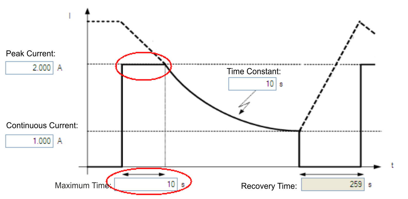
Peak current (MOTOR.IPEAK) along with coil thermal constant (MOTOR.CTFO) are used to determine the maximum time the motor can sustain peak current. The maximum time (IL.MFOLDD) is displayed in the Foldback view as shown below:
Motor Foldback Ramp
Once the maximum time for motor peak current has elapsed, if the move profile still demands peak current from AKD, the drive will exponentially lower the current applied to the motor. The Time Constant (IL.MFOLDT) dictates the profile. A smaller time constant represents a steeper decline in current applied to the motor.
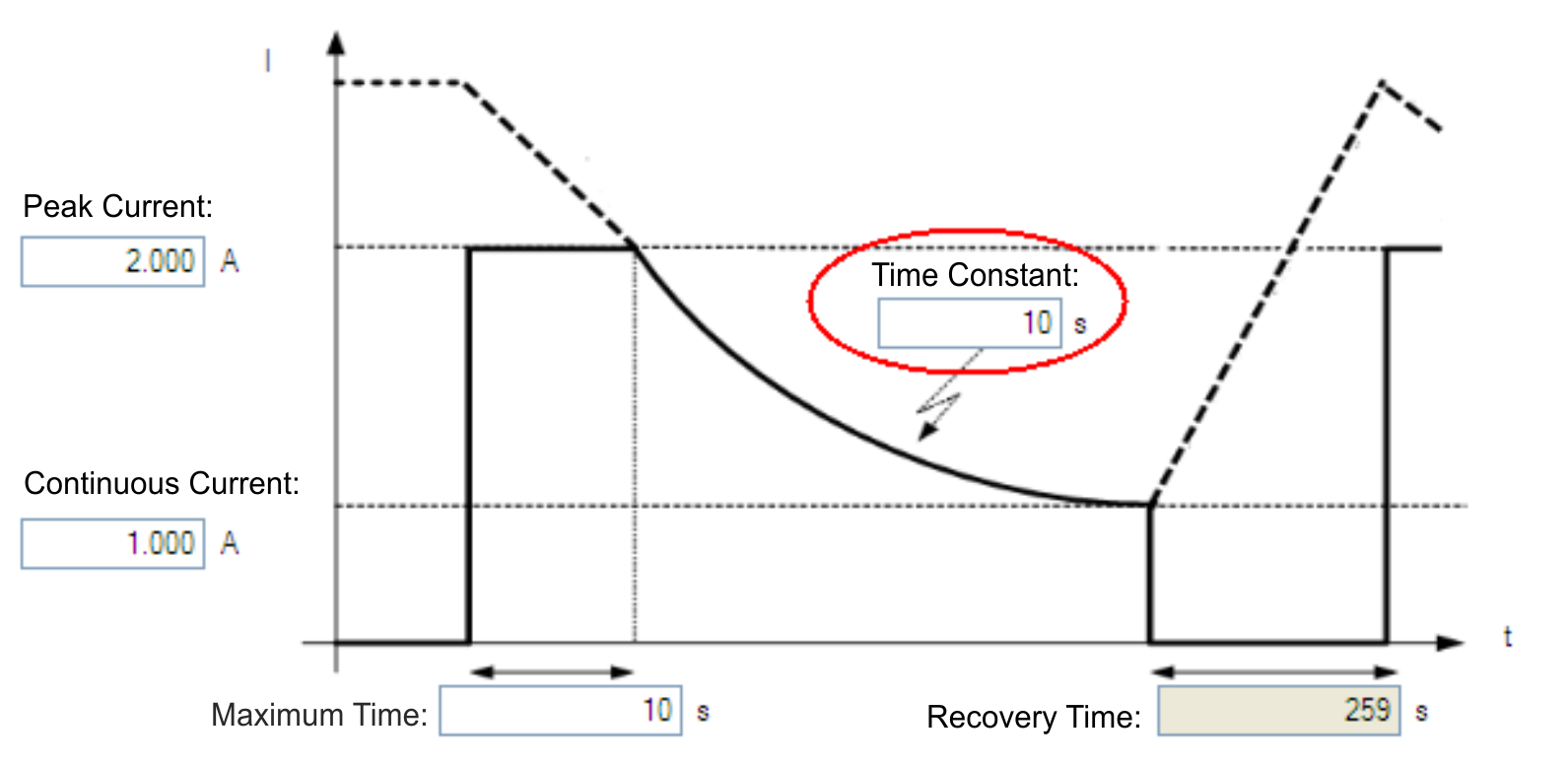
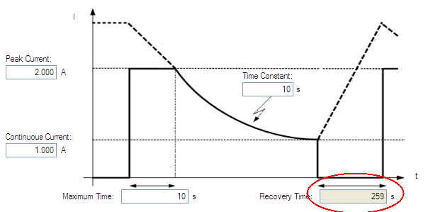
Motor Recovery
Once the peak motor current available has reached the continuous current of the motor, the motor needs Recovery Time (IL.MFOLDR) to cool down. Full Recovery Time (IL.MFOLDR) at 0 current is required for the motor to reach full maximum capacity in the shortest amount of time. The drive can command a current less than continuous current to continue driving the load, but the recovery time for full maximum capacity is increased.
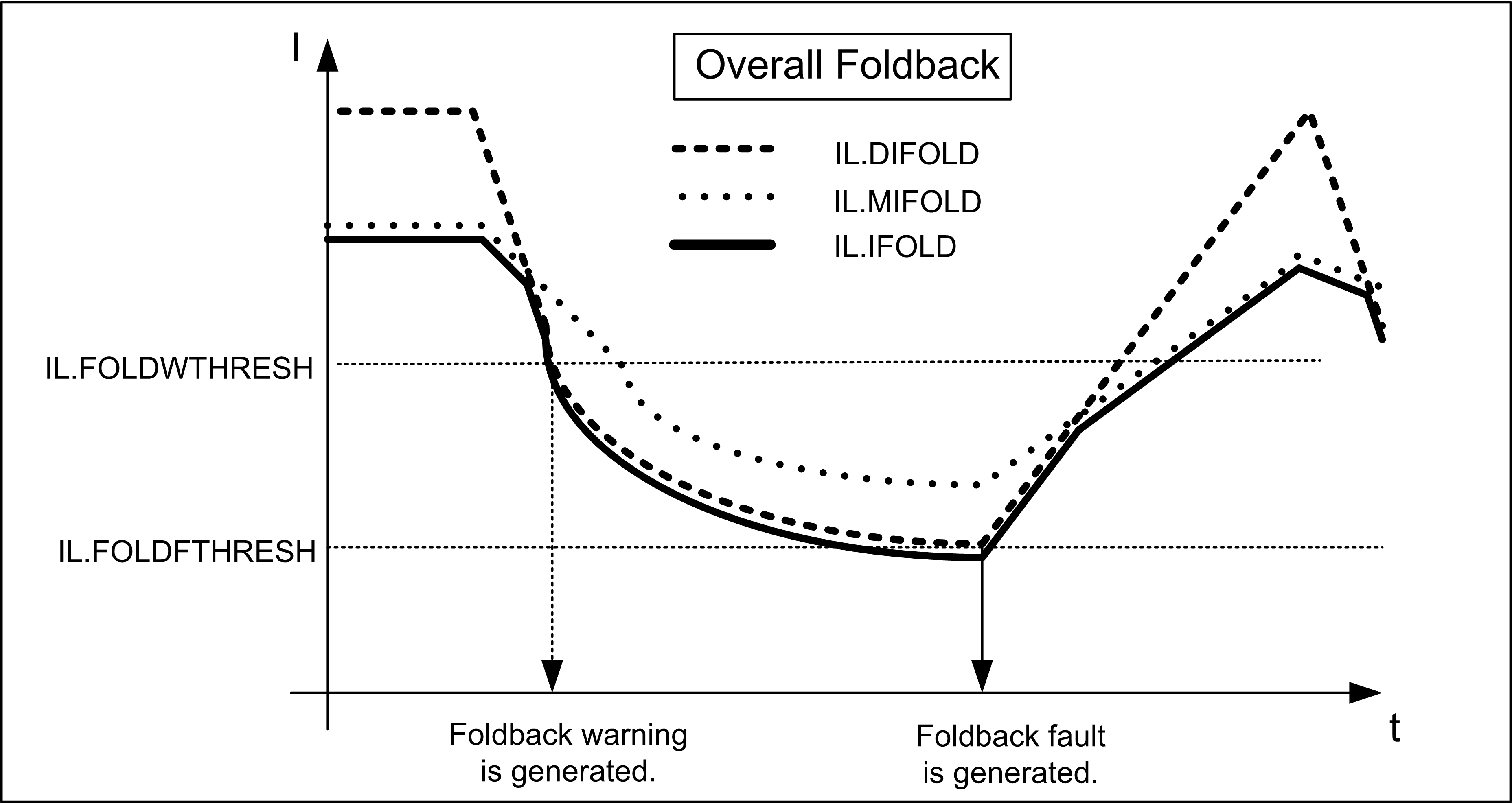
Overall Foldback
The overall limit is the momentary minimum value between the drive foldback and the motor foldback. The overall foldback is shown in the diagram below. You can set the warning and the fault levels as shown in the diagram.