Homing
Overview
Homing is used to mechanically move a motor (connected to a mechanism) to a specific location on the machine, referred to as “home”. Motion tasks then use this home as a reference point for movements that must base a known position on this reference point. Motor movement is usually controlled by a variety of limit switches (end of travel) and a home reference switch. Using these reference points with the logic of the drive allows the machine to find and set the home reference point.
Using Homing
The AKD includes a variety of homing methods (set with HOME.MODE) to accommodate your machine needs:
- Home using current position (HOME.MODE 0)
- Find limit input (HOME.MODE 1)
- Find input limit then find zero angle (HOME.MODE 2)
- Find input limit then find index (HOME.MODE 3)
- Find home input (HOME.MODE 4)
- Find home input then find zero angle (HOME.MODE 5)
- Find home input then find index (HOME.MODE 6)
- Find zero angle (HOME.MODE 7)
- Move until position error exceeded (HOME.MODE 8)
- Move until position error exceeded, then find zero angle (HOME.MODE 9)
- Move until position error exceeded, then find index (HOME.MODE 10)
- Find index signal (HOME.MODE 11)
- Home to home-switch, including mechanical stop detection (HOME.MODE 12)
- Home to feedback position (HOME.MODE 13)
- Home to home-switch for rotary applications (HOME.MODE 14)
- Find next feedback zero position (HOME.MODE 15)
- Find home input with dual edges (HOME.MODE 16)
- Absolute Mode - Calculate and save offset (HOME.MODE 17)
- Find home input, then find next feedback zero position (HOME.MODE 18)
Each of these homing methods offers a different way to achieve a home reference point based on your particular system mechanics. All homing methods provide the options of adjusting the acceleration, deceleration, and speed for homing moves. In addition, once the homing move is completed, you can either set an offset position or make an offset move as required. Homing modes, guidance for mode selection, and homing examples are included in Selecting and Using Homing Modes.
-
-
When using any of the methods that use homing switches and limits, please refer to the Input/Output section for proper wiring techniques.
Home Default Window
The Home window provides a means to select your homing method and configure the homing settings. This window also provides a simple controls to start homing and confirm homing success.
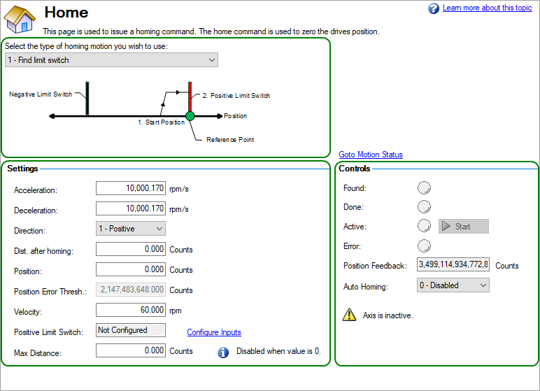
Mode Selection:
Use this box to select the appropriate homing mode. Homing modes are described below in Selecting and Using Homing Modes. The active options in the Settings area change depending on the homing mode selected.
Settings:
- Acceleration: Sets the acceleration ramp used during the homing procedure.
- Deceleration: Sets the deceleration ramp used during the homing procedure.
- Direction: Sets the start direction for homing movement.
- Distance: Sets a prescribed distance you want the motor to move once the home reference point is found. A zero value (default) corresponds to the axis actively returning to the defined position found during the homing process.
- Position: Sets the current position to a prescribed value once the home reference point is found.
- Position Lag: Sets the position error threshold, which is used for indicating home reference when using the hardstop modes 8 and 9.
- Velocity: Sets the initial velocity used for homing moves.
- Velocity Factor: In modes where a limit is reached, and direction is reversed, the velocity factor allows you to reduce the velocity as a precentage of the homing velocity.
- Positive/Negative Limit Switch/Home Reference/Peak Current: These fields appear based on the mode selected. For homing to limits and home reference, this field will indicate how the digital inputs are configured as well as provide a link to the digital input page. For Homing to a hard stop, the Peak Current field allows you to set the peak current limit desired during homing.
Controls:
- Found: When the home reference is found, then this indicator is green.
- Done: When the home move is complete, this indicator is green.
- Active: This indicator will be green while the Home move is taking place.
- Error:This indicator will be red if something in the homing sequence failed.
- Position Feedback: This window reports the current value for PL.PFB.
- Auto Homing: Allows the system to auto-home on power up.
- Start/Stop: Click this button to start or stop the selected homing method.
Selecting and Using Homing Modes
Using the current position is the most basic homing method. This method simply uses the current position of the motor as the home point reference. Two values allow you to further define homing with this method:
- Distance: A value other than zero will cause a movement of the motor the distance entered in counts (or other units based on your units settings). You can use this to establish a home point at some prescribed distance from the initial starting position of the motor. This home will be at the offset distance entered from zero.
- Position: You can use this parameter to set the value of the home position other then zero. This allows you to offset your home reference away from zero. PL.FB will be set to the value you enter when the motor reaches the home reference point (based on the method selected).
The distance and position offsets are available and behave similarly on all of the homing types. The motor will either move an additional distance (distance value) after it finishes the homing method, or set the position to the amount entered in the position value.
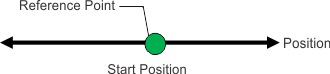
Use the current position as home and have the motor end motion 180 degrees from home:
- Select Mode 0 from the drop-down box.
- Enter 180 into the Distance box.
- Click Start.
- The motor will move 180 degrees from the start position. The Position Feedback box (PL.FB) will show 180 (the motor is now sitting 180 degrees from home).
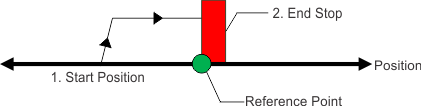
The find limit input mode creates a move to a limit input. This method can be used if you have a positive or negative limit switch available that you want to establish as a home reference point.
-
-
Limit switches should be set to Active Low (when switch power is lost, no current is flowing, and the drive homes at the point of the loss in power of the limit switch).
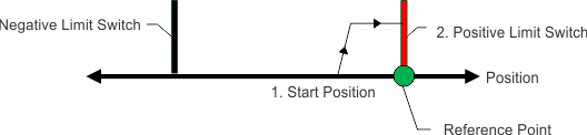
The sequence of this homing mode is as follows:
- The motor starts to move in the positive or negative direction, depending on the value you set in the Home screen (in the Settings section, Direction box).
- The motor stops as soon as the hardware limit switch has been detected and then reverses direction.
- The home position is set when the limit switch is no longer active. The actual and command position of the drive is immediately set to the home position value (HOME.P) and the motor ramps down to zero velocity. The axis is then moved to the position (HOME.P) + distance offset (HOME.DIST).
The values for distance and position can be used as described in homing mode 0.
-
-
When homing to a limit switch, the limit switch must remain in the triggered state while the motor decelerates to zero and begins to reverse. A very low acceleration rate combined with a high approach velocity may overshoot the switch and cause it to become active. This action will cause a homing error fault.
Use the positive end of travel limit as home reference, and then set this position to be -20 degrees.
1. Select Mode 1 from the drop-down box and enter 20 into the Position box.
2. Set the direction to positive. When Start is selected, the motor will move until it encounters the positive
end of travel switch.
3. As soon as the switch is triggered, the motor will reverse direction until the switch is no longer active.
4. As soon as the switch is no longer active, the position will be set to -20 degrees and the motor will ramp
to 0. Depending on the velocity you are homing with, and the settings of the acceleration/deceleration
ramps, the position feedback will be close to the position you entered.
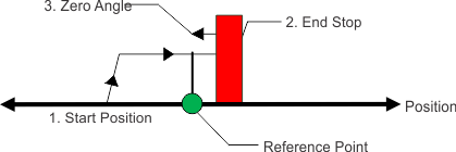
Similar to the Find Input Limit method, the find input limit then find zero angle mode follows the same steps, but upon completion of the move, it continues to move to find the zero angle reference of the motor.
-
-
Limit switches should be set to Active Low (when switch power is lost, no current is flowing, and the drive homes at the point of the loss in power of the limit switch).
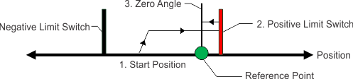
The specific steps are as follows:
- The motor starts to move according to the direction (HOME.DIR) setting.
- The motor stops as soon as the hardware limit switch has been detected and changes direction of movement.
- The home position has been found as soon as the hardware limit switch is no longer active. The actual and the command position of the drive will immediately be set to the HOME.P value plus distance to the mechanical zero angle of the feedback device according to the current direction.
- The motor moves to the home position (HOME.P) plus the distance move offset is applied (if present), which is located at the mechanical zero-angle of the feedback.
The values for distance and position can be used as described in home mode 0.
-
-
When homing to a limit switch, the limit switch must remain in the triggered state while the motor decelerates to zero and begins to reverse. A very low acceleration rate combined with a high approach velocity may overshoot the switch and cause it to become active. This action will cause a homing error fault.
Use the positive end of travel limit as home reference and then move to the zero angle of the motor
- Use the positive end of travel limit as home reference and then move to the zero angle of the motor.
- Select Mode 2 from the drop-down box.
- Set the Direction to Positive.
- When Start is selected, the motor will move until it encounters the positive end of travel switch.
- As soon as the switch is triggered, the motor will reverse direction and move to the zero angle of the motor.
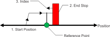
Similar to the Find Input Limit method, this follows the same steps, but upon completion of the move, it continues to move to find the index pulse of the motor. This method can only be used with feedback devices that have an index pulse such as incremental encoders and analog sine encoders with an index channel (Feedback selection 10, 11, 20, 21). This method requires that Capture Mode is turned on in the home screen. With Mode 3 selected, a Set Capture button appears (see arrow below). Click Set Capture to set the Position Capture mechanism correctly for proper homing with an index pulse.
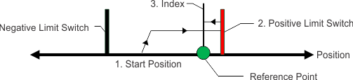
Once homing is triggered, the homing routine is performed as follows:
- The motor starts to move according to the HOME.DIR setting.
- The motor stops as soon as the hardware limit switch has been detected and changes direction of movement.
- The motor ramps down to a reduced velocity as soon as the hardware limit switch is no longer active (please refer also to HOME.FEEDRATE). The drive is searching for the index-signal during this time. The home-position has been found as soon as the index-signal has been detected by the drive.
- The actual and the command position of the drive will be set to the HOME.P value as soon as the index pulse is found. The drive then ramps down to velocity 0. The axis is then moved to the position (home.p) + distance offset (home.dist).
-
-
When homing to a limit switch, the limit switch must remain in the triggered state while the motor decelerates to zero and begins to reverse. A very low acceleration rate combined with a high approach velocity may overshoot the switch and cause it to become active. This action will cause a homing error fault.
Use the positive end of travel limit as home reference, and then move to the index reference of the motor feedback device at 50% of the original home velocity.
- Select Mode 3 from the drop-down box.
- Set the Direction to Positive.
- In the Home screen click Set Capture.
- Set the velocity factor to 50%.
- When Start is selected, the motor will move until it encounters the positive end of travel switch. As soon as the switch is triggered, the motor will reverse direction, decelerate to a reduced velocity based on the Velocity Factor value, and move until the motor encounters the index pulses of the feedback device.
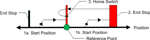
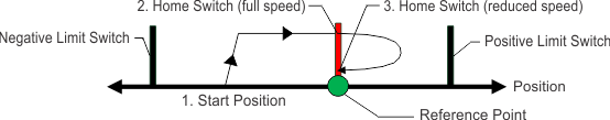
Homing Mode 4 establishes the home reference based on an external home switch connected to a drive digital input (DINx.MODE - 11 Home Reference).
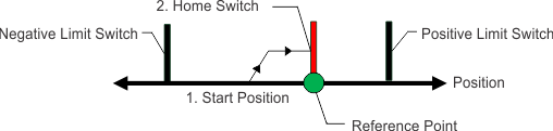
The sequence of this homing mode is as follows:
- The motor starts to move according to the direction (HOME.DIR) setting.
- The home position has been found as soon as the home-switch becomes active while traveling in the selected direction of motion (HOME.DIR). The actual and command position of the drive will immediately be set to the position (HOME.P) value and the motor ramps down to velocity 0. The axis is then moved to the position (home.p) + distance offset (home.dist).
If the Home Reference Input is active when told to home, the drive does a reset and then the home sequence. The sequence of the reset:
- The motor moves in the opposite direction of HOME.DIR
- When the home switch is not active, the motor ramps down to zero, and subsequently follows the sequence of the homing mode.
The hardware limit switches are monitored during the homing procedure. The drive behaves as follows in case that a hardware limit switch is active before the home-switch has been activated:
- The motor changes the direction until the home switch is crossed.
- The motor ramps down to zero velocity and reverses direction again after crossing the home-switch.
- The home-switch will now be activated according to the direction (HOME.DIR) setting and when the home-position has been found. The actual and the command position of the drive will immediately be set to the position (HOME.P) value and the motor ramps down to zero velocity. The axis is then moved to the position (home.p) + distance offset (home.dist).
Move in the negative direction towards the home reference point and then move 180 degrees from the reference point
- Select Mode 4 from the drop down-box.
- Set the Direction to Negative and enter 180 for distance.
- Click Start.
- The motor moves until it encounters the home reference switch. As soon as the switch is triggered, the motor moves an increment of 180 degrees as desired.
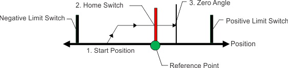
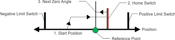
The sequence of this homing mode is as follows:
- The motor starts to move according to the Direction (HOME.DIR) setting.
- The home position has been found as soon as the home-switch becomes active while traveling in the selected direction of motion (HOME.DIR) and the zero angle of the resolver has been found. The actual and the command position of the drive will immediately be set to the Position (HOME.P) value plus the distance to the mechanical zero angle of the feedback device according to the current direction.
- The motor moves to the home Position (HOME.P) value plus the distance move offset is applied (if present), which is located at the mechanical zero-angle of the feedback.
If the Home Reference Input is active when told to home, the drive does a reset and then the home sequence. The sequence of the reset:
- The motor moves in the opposite direction of HOME.DIR
- When the home switch is not active, the motor ramps down to zero, and subsequently follows the sequence of the homing mode.
The hardware limit switches are monitored during the homing procedure. The drive behaves as follows in case that a hardware limit switch is active before the home-switch has been activated:
- The motor changes the direction until the home switch is crossed.
- The motor ramps down to zero velocity and changes afterwards the direction again after crossing the home-switch.
- The home-switch will now be activated according to the HOME.DIR setting and when the home-position has been found. The actual and the command position of the drive will immediately be set to the position (HOME.P) value plus distance to the mechanical zero angle of the feedback device according to the current direction.
- The motor moves to the home Position (HOME.P) value plus the distance move offset is applied (if present), which is located at the mechanical zero-angle of the motor feedback.
Move in the positive direction towards the home reference point and then move 60 degrees from the zero angle location.
- Select Mode 5 from the drop-down box.
- Set the Direction to Positive and enter 60 for distance.
- When Start is selected, the motor will move until it encounters the Home reference switch. As soon as the switch is triggered, the motor will move to the zero angle location plus an additional 60 degrees as desired.
Similar to the Home input method, this follows the same logic as the other homing methods, first completing the home to input method, and then finding the index pulse of the motor feedback.
This homing mode starts motion until a digital input, which is assigned to act as a home-switch, has been activated. The motor moves afterwards with a reduced velocity (HOME.FEEDRATE) until the index signal has been detected by the drive.
-
-
This method requires that Capture Mode is turned on. This is done in the home screen. With Mode 6 selected, a “Set Capture” button will appear (see arrow below). Pressing the button sets the Position Capture mechanism correctly for proper homing with an index pulse..

The home-switch must be activated according to the setting of the HOME.DIR setting.
The sequence of this homing mode is as follows:
- The motor starts to move according to the HOME.DIR command.
- The motor decelerates to a reduced velocity according to the HOME.FEEDRATE setting as soon as the home-switch becomes active during a motion in direction of the HOME.DIR setting.
- The actual and the command position of the drive will immediately be set to the HOME.P value as soon as the index-signal has been detected. The motor decelerates until velocity 0 has been reached.
If the Home Reference Input is active when told to home, the drive does a reset and then the home sequence. The sequence of the reset:
- The motor moves in the opposite direction of HOME.DIR
- When the home switch is not active, the motor ramps down to zero, and subsequently follows the sequence of the homing mode.
The hardware limit switches are monitored during the whole homing procedure. The drive behaves as follows in case that a hardware limit switch is active before the home-switch has been activated:
- The motor changes the direction until the home-switch is crossed.
- The motor ramps down to zero velocity and changes direction again after crossing the home-switch.
- The home-switch will now be activated according to the HOME.DIR command. The motor decelerates to a reduced velocity according to the HOME.FEEDRATE setting as soon as the home-switch becomes active.
- The actual and the command position of the drive will immediately be set to the HOME.P value as soon as the index-signal has been detected. The motor decelerates until zero velocity has been reached. The axis is then moved to the position (HOME.P) + distance offset (HOME.DIST).
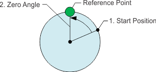
The sequence of this homing mode is as follows:
- The home value is immediately found by the drive and the actual and the command position of the drive will immediately be set to the Position (HOME.P) value plus the distance to the mechanical zero angle of the feedback device according to the current direction.
- The motor moves to the home Position (HOME.P) value, which is located at the mechanical zero-angle of the feedback.
- Select Mode 7 from the drop-down box.
- Set the direction to Positive.
- When Start is selected, the motor will move to the zero angle location.
This method is also referred to as move to hard or mechanical stop. The AKD has several options related to this method as well. For this basic method, the motor will move until it encounters a hard stop, causing the position error to exceed a specific threshold you set. Once the threshold is exceeded, the motion stops and home reference is established. You can use the Distance or Position as described initially in this section.
-
-
Be sure to choose the direction appropriately to move off of the stop if using the distance offset.
The sequence in this homing mode is as follows:
- As this home move is initiated, the motor will move according to the Direction (HOME.DIR) value until the positon error exceeds the Position Lag (HOME.PERRTHRESH) value.
- The motor is now at home position (HOME.P) value.
- Select Mode 8 from the drop-down box.
- Set the Direction to Positive, Position Lag to 30 degrees and Peak Current to 1.
- When Start is selected, the motor will move to the hard stop with a peak current of 1 amp.
- As the position error exceeds the 30 degrees, the home Position (HOME.P) is set.
The sequence in this homing mode is as follows:
- As this home move is initiated, the motor will move according to the Direction (HOME.DIR) value until the positon error exceeds the Position Lag (HOME.PERRTHRESH) value.
- The home value is immeadiately found by the drive and the actual and the command position of the drive will be set to the Position (HOME.P) value plus the distance to the mechanical zero angle of the feedback device according to the current direction.
- The motor moves to the home Position (HOME.P) plus the distance move offset is applied (if present) value, which is located at the mechanical zero-angle of the feedback.
- Select Mode 9 from the drop-down box.
- Set the Direction to Positive, Position to 180, Position Lag to 30 degrees and Peak Current to 1.
- When Start is selected, the motor will move to the hard stop with a peak current of 1 amp. As the position error exceeds the 30 degrees, the home Position (HOME.P) is set and the Position will be set to 180.
This method is similar to HOME.MODE 8, but looks for the index pulse after it encounters the hard stop. For this method, the motor will move until it encounters a hard stop, causing the position error to exceed a specific threshold that you set. Once the threshold is exceeded, the motion will reverse and look for an index pulse.
This method can only be used with feedback devices that have an index pulse such as incremental encoders and analog sine encoders with an Index channel (Feedback selection 10, 11, 20, 21). This method requires that Capture Mode is turned on in the home screen. With Mode 10 selected, a Set Capture button appears (see arrow below). Click Set Capture to set the position capture mechanism correctly for proper homing with an index pulse.
- Motor advances into the mechanical stop and then reverses direction.
- The motor is searching for the index pulse during this time.
- If the motor finds the Index pulse, then the Home-position is found.
- The actual and the command position of the drive will be set to the HOME.P value as soon as the index signal is found. The drive then ramps down to velocity 0.
- If another mechanical stop is found before the Index signal, then the homing sequence will fail and the system needs to be reviewed for proper wiring.
- Select mode 10 from the drop-down box.
- Set the direction to positive.
- In the home screen click Set Capture.
- Set position lag and peak current values based on your application requirements.
- When start is selected, the motor moves in the positive direction until a hard stop is encountered.
- The motor reverses and moves until it encounters the index reference and then it stops.
- If another hard stop is encountered before the index reference, home fails.
Unlike Homing Mode 3, the Home position is set as soon as the index pulse is found, irrespective of the direction of motion.
This method can only be used with feedback devices that have an index pulse such as incremental encoders and analog sine encoders with an Index channel (Feedback selection 10, 11, 20, 21). This method requires that Capture Mode is turned on in the home screen. With Mode 11 selected, a Set Capture button appears (see arrow below). Click Set Capture to set the position capture mechanism correctly for proper homing with an index pulse.
Once homing is triggered, the homing routine is performed as follows:
- The motor starts to move according to the HOME.DIR setting.
- The Motor is searching for the index pulse during this time.
- If the Motor finds the Index pulse, then the Home-position is found.
- The actual and the command position of the Drive will be set to the HOME.P value as soon as the index-signal is found. The Drive then ramps down to velocity 0 and moves back to index position.
- If the Limit switch is active before Index signal, then the Motor changes the direction and then repeats steps 3 and 4.
- Select Mode 11 from the drop-down box.
- Set the Direction to Positive.
- In the home screen press the “set capture” button.
- When Start is selected, the motor will move until it encounters the index reference and then it stops.
- If Limit switch is encountered before Index reference, the Motor changes direction and searches for Index signal in the opposite direction.
Unlike Homing Mode 3, the Home position is set as soon as the index pulse is found, irrespective of the direction of motion.
This homing mode starts a motion until a digital input, which is assigned to act as a home switch, has been activated. The home switch must be activated according to the setting of the HOME.DIR setting. The home position is found as soon as the home-switch was activated during a motion in direction of the HOME.DIR setting.
The sequence of this homing mode is as follows:
- The motor starts to move according to the HOME.DIR setting.
- The home position has been found as soon as the home-switch becomes active during a motion in direction of the HOME.DIR setting. The actual- and the command position of the Drive will immediately be set to the HOME.P value and the motor ramps down to velocity 0.
This homing mode is similar to the homing mode 4, but checks if the motor hits a mechanical stop instead of the hardware limit switches. A mechanical stop is detected as soon as the absolute value of the position error (PL.ERR) is larger than the position error threshold (HOME.PERRTHRESH) setting. The current command value is limited to the HOME.IPEAK value during the homing process. The motor behaves as follows when a mechanical stop has been detected before the home switch was found:
- The motor changes the direction until the home switch is crossed.
- The motor ramps down to velocity 0 and changes afterwards the direction again after crossing the home switch.
- The home-switch will now be activated according to the HOME.DIR setting and the home-position has been found. The actual and the command position of the drive is immediately set to the HOME.P value and the motor ramps down to velocity 0.
If the Home Reference Input is active when told to home, the drive does a reset and then the home sequence. The sequence of the reset:
- The motor moves in the opposite direction of HOME.DIR
- When the home switch is not active, the motor ramps down to zero, and subsequently follows the sequence of the homing mode.
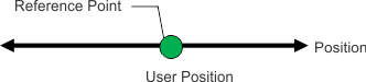
This mode should be selected when using a multi-turn feedback device with AKD. Since the feedback keeps track of its value at all times, the drive takes the value of the feedback at power up. The homing flag is also set. Use auto-home with this mode (HOME.AUTOMOVE). The multi-turn device is initially referenced using FB1.OFFSET. This value is set in the drive using the terminal screen and will need to be saved to the drive. Single-turn absolute devices can also utilize this mode if they are used in applications like a rotary index table where the entire range is within 360 degrees.
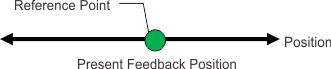
Motion in this mode continues until a digital input assigned to act as a home switch has been activated. The home position is found as soon as the home-switch is activated during motion in the direction set by HOME.DIR
The sequence of this homing mode is as follows:
- The motor starts to move in the direction set by HOME.DIR.
- The home position is found as soon as the home-switch becomes active during a motion in direction of the HOME.DIR setting. The actual position and command position of the drive will immediately be set to the HOME.P value and the motor will ramp down to velocity 0.
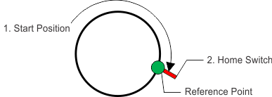
This homing mode is similar to homing mode 12, but it will ignore hardware limit switches as well as mechanical stops. It will also always turn in the direction set by HOME.DIR, even when the reference switch is active at the beginning of the homing procedure. Use HOME.MAXDIST to prevent the motor from turning endlessly. HOME.DIST is not applied to the homing mode 14. The axis does not return to the zero position (or zero position + home.distance) as it does for other home modes, such as mode 4. This ensures that the homing motion is done only in the direction set by HOME.DIR.
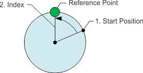
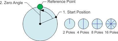
This homing mode is similar to homing mode 7 (Find Zero Angle), however, if the feedback device has more than 1 pole pair (2 poles), the motor will home to the next pole pair. The number of individual poles in a feedback device is set by FB1.POLES.
-
-
If the feedback device has 2 poles (1 pole pair) then this mode will operate exactly the same as homing mode 7.
This homing mode is similar to homing mode 4, but is better for applications which home at high velocity and require high accuracy. The axis is homed in the direction of HOME.DIR with velocity HOME.V. Once the axis detects the home position the direction is changed and the axis returns to the home position with a reduced velocity defined by HOME.V and HOME.FEEDRATE.
In this mode the drive will first execute an absolute homing and then calculate and store a value for FB1.OFFSET, so that the current position becomes the position specified by the user through HOME.P. The value of FB1.OFFSET is automatically saved in non-volatile memory, so that the drive does not have to be re-homed after power cycle when using an absolute feedback device.
Home mode 18 works similar to home mode 5, however, if the feedback has more than 1 pole pair (2 poles), the motor will home to the next pole pair.
Using Homing: Advanced
The various homing methods in the AKD offer several options for setting up your home reference. When using any of the methods that use homing switches and limits, please refer to the Input/Output section for proper wiring techniques.
Related Parameters and Commands
CAP0.MODE, CAP1.MODE : Sets index capture method