Capture
Capture is the process of capturing a precise position of an axis or feedback at the edge of a digital input. The time of the edge is also stored.
The AKD2G drive supports two user capture channels, CAP1 and CAP 2. Each channel can capture one position and one time on the transition of a trigger input or the index pulse from some position feedback devices. Each capture channel can be used with any feedback or axis and any digital input.
Optional pre-conditions allow filtering of which input edge will be used to capture the position. For example, you can trigger the first rising edge of DIN3 after another input DIN4 goes high.
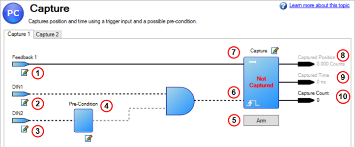
Each capture channel is arranged as follows:
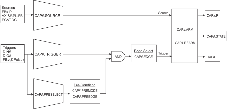
The position is a sampled with dedicated hardware in the drive. When using the inputs that use fast optocouplers, DIN1 or DIN2, or the DIO channels, then the accuracy of the captured position will be better than 0.0038°. When using the other digital inputs that have slow optocouplers, DIN3 to DIN2, then the added latency on these inputs increases the worst-case error to 0.24°. These numbers assume the filter turned off ("DIN#.FILTER" is 0).
For a typical case where the axis is at a constant speed of 2000 rpm and using DIN1 as the trigger the accuracy would be of the order of 0.00048° which is significantly better than the accuracy of most feedbacks.
It is recommenced to set the input filter, "DIN#.FILTER" or "DIO#.FILTER", for the trigger source to zero to disable the input filter. If you configure an input filter, this additional delay to the trigger will make the captured position less accurate.
When using auto-rearm the smallest time between consecutive triggers is 125 µs.
The following keywords can be used to configure and then retrieve the captured positions.
| Keyword | Summary |
|---|---|
| CAP#.ARM | Arms or disarms the capture channel. |
| CAP#.COUNT |
The number of capture events that have happened |
| CAP#.EDGE | Selects which edge of the trigger input to use. |
| CAP#.P | The captured position. |
| CAP#.PREEDGE | Selects the edge used by precondition |
| CAP#.PREMODE | Selects the type of precondition. 0 is no precondition. |
| CAP#.PRESELECT | Selects the digital input is used by the precondition. |
| CAP#.REARM | Selects auto rearm instead of single shot. |
| CAP#.SOURCE | Selects what will be captured on the trigger edge. |
| CAP#.STATE | Reports if the channel is waiting for the trigger or is triggered. |
| CAP#.TRIGGER | Which digital input will trigger the capture. |
Typical Uses of Capture
Position capture is used in precision environments where the motor may be moving at a high velocity, and you must know exactly where the motor was when an input changes state.
Motion Tasking - Registration Moves
See Registration Moves.
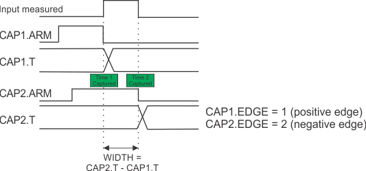
Measure Pulse Width
You can use the captured times to measure the width of a digital input pulse.
To measure the width of a pulse, or the time between two pulses, you can use both sets of CAP# keywords. Set one to capture the first edge and the other to capture the second edge. The pulse width is the difference between the two captured times.
CANopen (EtherCAT or CAN bus) Touch Probes
AKD2G does not use CAP1 or CAP2 to provide the CANopen touch probes. Two touch probes per axis are fully supported over EtherCAT or CAN bus with their own dedicated hardware in the drive.
Reference
|
|
|
| Element | Property | Settings | Description | Parameter |
|---|---|---|---|---|
| Source for Capture # Configuration | Source | 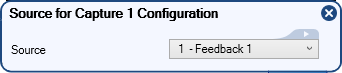
|
Select the source of the captured position. | CAP#.SOURCE |
| Trigger Input for Capture # Configuration | Input | 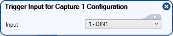
|
Select which digital input will trigger the capture. | CAP#.TRIGGER |
| Pre-Condition Input for Capture # Configuration | Input | 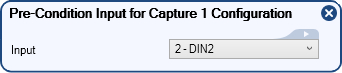
|
Select the digital input that is used by the precondition. | CAP#.PRESELECT |
| Pre-Condition for Capture # Configuration | Pre-Condition Mode | 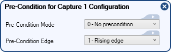
|
Select pre-condition for the capture.
|
CAP#.PREMODE |
| Pre-Condition Edge | Select the edge used by the precondition.
|
CAP#.PREEDGE | ||
| Arm button |
  |
Arm or disarm the capture channel. | CAP#.ARM | |
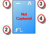
| Capture block |
|
This item performs the logic necessary to calculate the capture state. This item provides four pieces of information.
|
CAP#.STATE | |
| Capture # Configuration | Arming Mode | 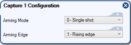
|
Select how the channel is armed.
|
CAP#.REARM |
| Arming Edge | Select which edge of the trigger input to use.
|
CAP#.EDGE | ||
|
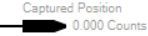
Capture Position |
Output
|
|
This output shows the captured position. |
|
|
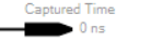
Captured Time |
Output
|
|
This output shows the drive's local time at capture. |
|
| Capture Count | Output |
|
This output shows the capture count. | CAP#.COUNT |
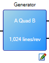
| Editable Icon |

|
This icon signifies that a block is editable. Clicking the icon opens a Property Editor, where data may be set.
The Editable icon may be associated with Arrows or Boxes, as seen below.
|