


Foldback
Foldback
The foldback feature in the AKD2G protects both the motor and the drive from overheating. Two current foldback algorithms run in parallel in the drive: the drive foldback algorithm and the motor foldback algorithm. Each algorithm uses different sets of parameters. Each algorithm has its own foldback current limit, AXIS#.IL.DIFOLD (drive foldback) and AXIS#.IL.MIFOLD (motor foldback). The overall foldback current limit is the following at any moment:
(AXIS#.IL.IFOLD = min (AXIS#.IL.DIFOLD, AXIS#.IL.MIFOLD, AXIS#.IPEAK).
Foldback is not the same as current limits. Instantaneous current limits for the drive are set by the positive peak current (AXIS#.IL.LIMITP) and negative peak current
(AXIS#.IL.LIMITN) in the Limits view in WorkBench. The foldback algorithms may reduce the current output to the motor in spite of the current limit settings.
Drive Foldback
The drive foldback algorithm monitors current feedback; since this is a monitoring function, the drive foldback parameters are not user configurable. If the current feedback exceeds the continuous current rating of the drive (AXIS#.ICONT), then the algorithm decreases the current to the AXIS#.ICONT level. For example, under a step command input condition, the foldback algorithm allows maximum peak current (AXIS#.IPEAK) output from the drive for a short period of time (5 seconds when current has been zero for a long time and then it jumps to AXIS#.IPEAK) after which the drive begins an exponential foldback (with time constant of 2.5 seconds) of the current to the drive’s continuous current.
It takes a few seconds for the exponential decay to drop from the drive’s peak current to its continuous level. A recovery time, when the feedback current is below AXIS#.ICONT level, is required to allow current above AXIS#.ICONT level again. A recovery time with 0 current allows the drive to apply AXIS#.IPEAK current again.
The drive foldback is in full recovery mode after boot or power cycle. The Drive Foldback parameters are automatically set and do not need user modification.
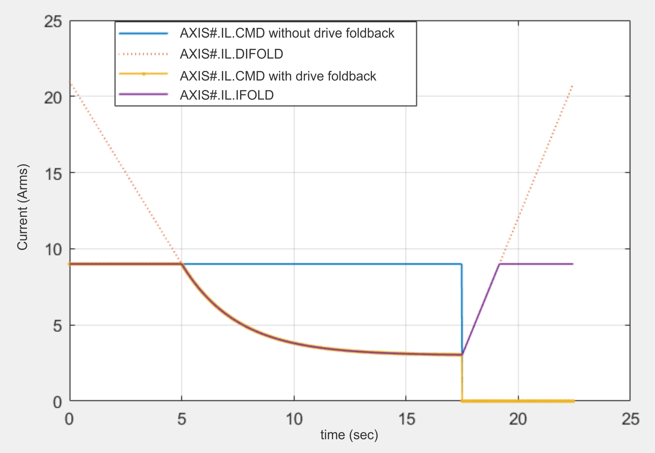
The following figure depicts typical AXIS#.IL.CMD and AXIS#.IL.DIFOLD waveforms for a drive with
-
AXIS#.IPEAK = 9 Arms
-
AXIS#.ICONT = 3 Arms
Setting Up Motor Feedback
Motor foldback is set up automatically when using a plug and play motor or when a particular motor is selected from the WorkBench database.
If you are using a custom motor, use the Motor view in WorkBench to set custom values needed for foldback configuration. The parameter entries required for the drive to apply motor foldback protection properly are coil thermal constant (AXIS#.MOTOR.CTF0), peak current of the motor (AXIS#.MOTOR.IPEAK), and continuous current of the motor (AXIS#.MOTOR.ICONT). These values are used to setup the algorithm for motor foldback.
Setting Fault and Warning Levels
AXIS#.IL.DIFOLD and AXIS#.IL.MIFOLD are the variables that are constantly updated by the drive and motor foldback algorithms, respectively. AXIS#.IL.IFOLD is the minimum of AXIS#.IL.DIFOLD, AXIS#.IL.MIFOLD and AXIS#.IPEAK and it represents the overall current limit. As current is applied above the drive or motor continuous rating, the capacity for the application of peak current starts to decrease; therefore, the overall current limit is actively decreased. If the move profile requires less than continuous current rating for a period of time, the Overall Current Limit begins to increase until it reaches the maximum foldback capacity once again (which is the maximum of AXIS#.IPEAK and AXIS#.MOTOR.IPEAK).
When the Overall Current Limit > Warning Level, a warning is triggered. The warning shows whether it is coming from the motor foldback algorithm or drive foldback algorithm. When Overall Current Limit > Fault Level, a fault is triggered and the drive power stage is disabled. The load then coasts to a stop. The fault shows whether it is coming from the motor foldback algorithm or drive foldback algorithm.
If User Fault Level (AXIS#.IL. FOLDFTHRUSHU) is set above AXIS#.IPEAK and AXIS#.MOTOR.IPEAK, the User Fault Level is ignored.


