


 Limits
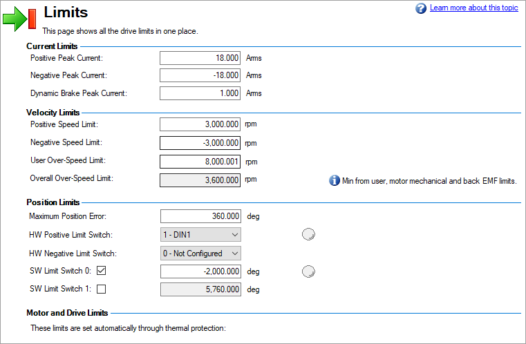
This screen allows you view and modify the various drive limits.
Position Limits
Software Limit Switches
Position limits can be set based on specific machine application requirements. Two software limits per axis are available which can be either the lower or upper position limit based on the value of AXIS#.SWLS.EN. If only one software limit switch is enabled, AXIS#.SWLS.EN = 1 or 2, then AXIS#.SWLS.LIMIT0 is the lower limit and AXIS#.SWLS.LIMIT1 is the upper limit. If both limit switches are enabled (AXIS#.SWLS.EN = 3), then whichever switch is set to a greater value is the upper limit switch and the other switch becomes the lower limit. In order for software limit switches to be active, an axis must have been homed.
With an axis in motion and software limit switches active, when position reaches a limit, a warning is generated, 6006: Warning: Positive Limit Switch triggered for the upper limit or 6007: Warning: Negative Limit Switch triggered for the lower limit and the axis will decelerate to stop.
Software limit switches may be used in applications where use of hardware limit switches is not feasible.
Hardware Limit Switches
Hardware limit switches can be used separate from or in combination with software limit switches. Hardware limit switches are connected to digital inputs on the drive and the corresponding DIN assigned as the source for the positive or negative travel limit using AXIS#.HWLS.POSSOURCE and AXIS#.HWLS.NEGSOURCE.
With an axis in motion, when a digital input acting as a source for a hardware limits is triggered, a warning is generated, 6006: Warning: Positive Limit Switch triggered for the upper limit or 6007: Warning: Negative Limit Switch triggered for the lower limit and the axis will perform a controlled stop with a deceleration ramp matching that specified by AXIS#.CS.DEC .
Reference
| Element | Property | Description | Parameter |
|---|---|---|---|
| Current Limits | Positive Peak Current | This parameter sets the positive user limit clamp value of the torque-producing q-component current command (AXIS#.IL.CMD ). | AXIS#.IL.LIMITP |
| Negative Peak Current | This parameter sets the negative user limit clamp value of the torque-producing q-component current command (AXIS#.IL.CMD ). | AXIS#.IL.LIMITN | |
| Dynamic Brake Peak Current | This parameter sets the maximum amplitude of the current for dynamic braking. | AXIS#.DBILIMIT | |
| Velocity Limits | Positive Speed Limit | This parameter sets the velocity command positive limit. | AXIS#.VL.LIMITP |
| Negative Speed Limit | This parameter sets the velocity command negative limit. | AXIS#.VL.LIMITN | |
| User Over-Speed Limit | This parameter sets the user overspeed fault threshold. | AXIS#.VL.THRESH | |
| Overall Over-Speed Limit | This parameter reports the overall overspeed fault threshold. | AXIS#.VL.VFTHRESH | |
| Position Limits | Maximum Position Error | This parameter sets the maximum position error. | AXIS#.PL.ERRFTHRESH |
| HW Positive Limit Switch | This parameter selects which digital input will be used as the positive limit switch input for an axis. An LED light is added to the view when a limit switch is defined. The light glows when the limit is active. | AXIS#.HWLS.POSSOURCE | |
| HW Negative Limit Switch | This parameter selects which digital input will be used as the negative limit switch input for an axis. | AXIS#.HWLS.NEGSOURCE | |
| SW Limit Switch 0 | These parameters sets the position value for a software limit switch, LIMIT0 or LIMIT1. An LED light is added to the view when a limit switch is defined. The light glows when the limit is active. | AXIS#.SWLS.LIMIT# | |
| SW Limit Switch 1 |


