


 Modulo Position
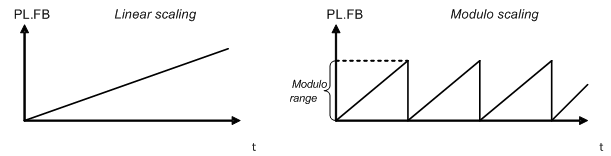
Modulo position is a function that simplifies rotational applications such as unidirectional rotating assembly tables. When enabled, the modulo axis feature converts several position-based parameters to fit in a defined modulo range. Once this range is defined, a given position value will roll over at the end of the modulo range and return to the beginning of the modulo range. This behavior affects some drive functions, which work with modulo-scaled position variables when the modulo-feature is enabled.
The following figure describes the progress of the actual position value (AXIS#.PL.FB ) for linear scaling and modulo scaling when the motor moves continuously in a positive direction:
Setting up the modulo axis in WorkBench
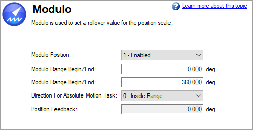
You can set up the modulo axis from the Modulo view in WorkBench.
In the image below the settings ensure AXIS#.PL.FB will always be 0-360 degrees.
|
Button or Box |
Description |
|---|---|
|
Modulo Position |
Enables or disables modulo (AXIS#.PL.MODPEN |
|
Modulo Range Begin/End |
Sets the beginning and end of the modulo range (AXIS#.PL.MODP1, AXIS#.PL.MODP2) |
|
Direction for Absolute Motion Task |
Sets the direction of an Absolute Motion task when Modulo is enabled. The direction can be set to always positive, or always move negative. The "Shortest Distance" mode will determine the shortest distance to the target and move in that direction. The "inside range" mode will move in the direction that allows the motor to stay in between the defined scale and therefore not to wrap around. Shortest Distance is more commonly used than Inside Range mode. (AXIS#.PL.MODPDIR) |
|
Position Feedback |
Reads and displays the position feedback (AXIS#.PL.FB ) |
Setting up the modulo axis from the Terminal
You can use the following parameters to configure the modulo-axis feature:
- AXIS#.PL.MODPEN: Enables or disables the modulo-axis feature.
- AXIS#.PL.MODP1: Defines either the beginning or the end of the modulo range, depending on whether this value is smaller or larger than AXIS#.PL.MODP2.
- AXIS#.PL.MODP2: Defines either the beginning or the end of the modulo range, depending on whether this value is smaller or larger than AXIS#.PL.MODP1 .
Parameters affected by the modulo axis
The following parameters are converted into modulo format when the values of these parameters are queried by a user, a fieldbus, or the software oscilloscope.
- AXIS#.PL.FB : The actual position of the drive is converted into modulo scaling.
- AXIS#.PL.CMD: The command position of the drive is converted into modulo scaling.
- CAP#.P: The actual position of the drive, which has been captured by the capture engine, is converted into modulo scaling.
-
- Feedback device position (FB#.P) will remain unaffected by the modulo settings.
Drive functions affected by modulo axis
Software limit switch
The software limit switches in the drive compare the actual position (AXIS#.PL.FB ) with threshold values. Motion is stopped when the actual position exceeds the software limits. Since AXIS#.PL.FB is affected by the modulo-axis feature, the software limit switches monitor the modulo-converted AXIS#.PL.FB value. Software limit switches with thresholds outside of the modulo range never limit motion.
Programmable limit switch
The programmable limit switches compare the actual position (AXIS#.PL.FB ) with selectable thresholds and then status flags are set to "true" when the actual position is currently within these position limits. The programmable limit switches monitor the modulo-converted AXIS#.PL.FB value. Programmable limit switches that are set outside the modulo-range never become active.
Action Table Position Feedback Source
The action table position feedback source uses the modulo-converted position AXIS#.PL.FB . Values outside the range of the modulo-range will not become active.
Motion tasking to absolute target positions
When modulo is enabled, absolute motion tasks assume that the command is modulo converted. Absolute motion tasks to target positions outside of the modulo range generate a warning, Faults and Warning Messages (Motion task target position is out of modulo range).
Using the modulo position feature with multiturn encoders
A special case exists for the following combinations of events:
- The drive is connected to a multiturn feedback device.
- The modulo axis feature is enabled.
- The selected modulo range does not fit as an integer in the range of the multiturn feedback.
- The application moves further than the total amount of multiturn feedback revolutions. In this case, problems occur because the multiturn feedback position overrun and a modulo range position rollover point does not occur at exactly the same position.
-
- If FB#.STOREMULTITURN.ENABLE = 1, absolute position can be restored even if modulo position is enabled.
After powerup of the drive, the actual position (AXIS#.PL.FB ) will be read from the multiturn feedback device. This position can be considered as a position within the feedback range as described in the figures below.
The following figure illustrates drive behavior when the selected modulo range fits as an integer within the multiturn feedback range. For simplicity, assume that one multiturn feedback range describes four feedback revolutions and the selected modulo range is set to two feedback revolutions.
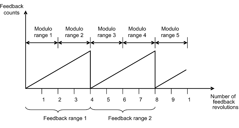
As described in the figure above, the selected modulo range of the drive is repeated exactly at the point where the connected multiturn feedback rolls over (Modulo range 1, 3, 5…). The application can move for several multiturn feedback ranges and the drive can recalculate the modulo position correctly after a power cycle. The positions within the modulo ranges represent the same value in modulo format for each feedback range.
Example
The modulo-converted position, which represents 5 or 9 feedback revolutions, corresponds to the modulo position, which represents 1 feedback revolution.
The next figure illustrates the drive behavior when the selected modulo range does not fit as an integer within the multiturn feedback range. For simplicity, assume that one multiturn feedback range describes four feedback revolutions and the selected modulo range is set to 2.5 feedback revolutions.
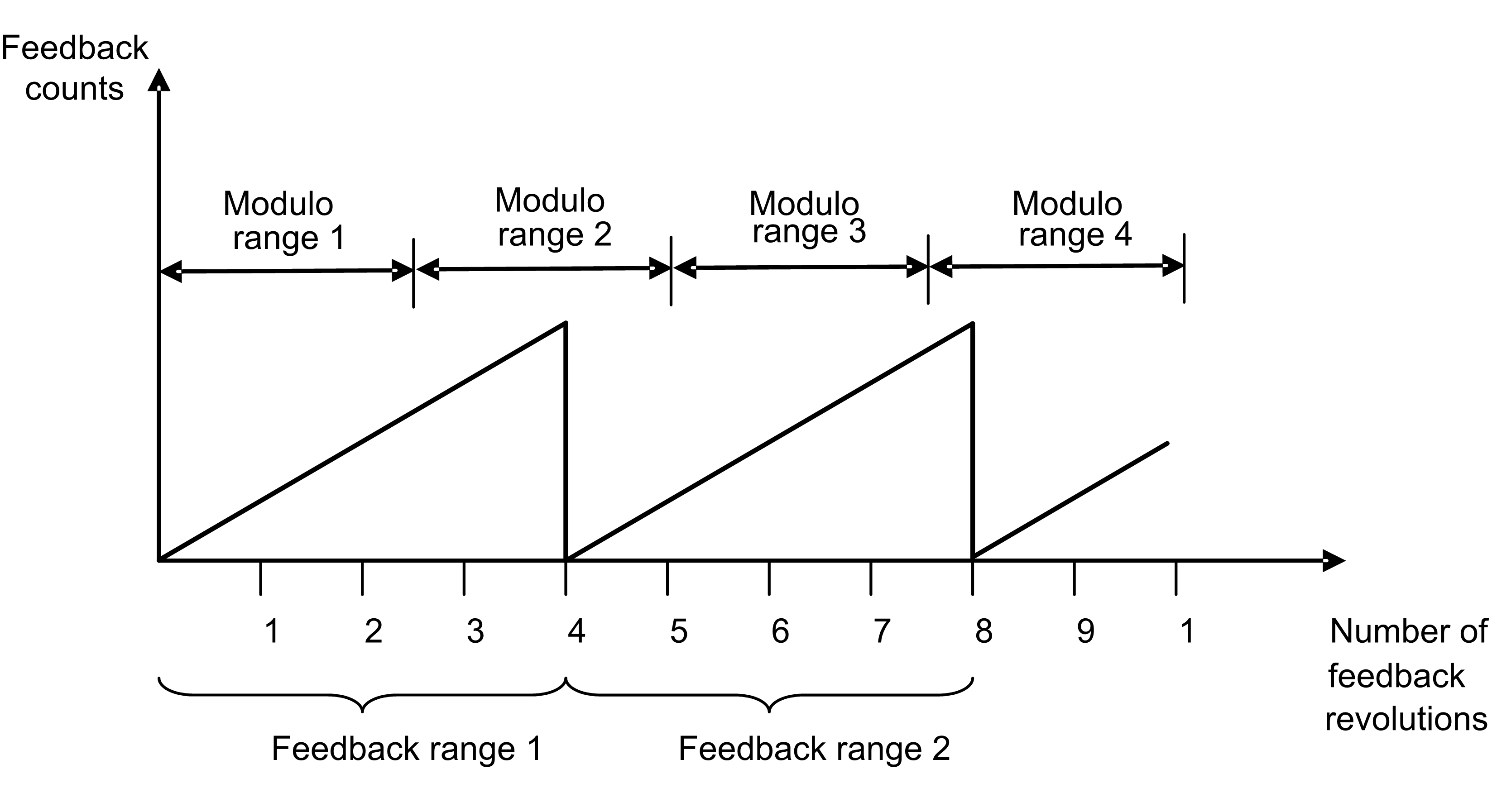
As described in the figure above, the selected modulo range is not repeated exactly at the place where the connected multiturn feedback rolls over. The application can move for several multiturn feedback ranges, but the drive cannot calculate the modulo position correctly after a power cycle.
Example
The modulo-converted position, which represents five feedback revolutions, does not correspond to the modulo-position, which represents one feedback revolution.


