Instability
A system is unstable if its open loop frequency response is 0 dB, -180°
If the Open Loop [G] gain is equal to 0 dB and the phase is -180° at the same frequency, the system is defined as Unstable.
Let’s analyze how a feedback system works (servos are feedback systems). Looking at the two cases where:
-
The Open Loop [G] response is 0 dB, 0°
-
The Open Loop [G] response is 0 dB, -180°
Instability: 0 Deg vs -180 Deg
How does a system perform when the Open Loop [G] response is 0 dB, 0 degrees?
-
The system performs the commanded move with the same amplitude and in phase.
-
The system performs the corrections with no delay.
-
The servo system corrections are perfect in magnitude.
The control loop is operating at peak performance
Note: While this is the absolute best case for a control loop the system response is not perfect. This is another case for feed forwards.
Review:
-
The Closed Loop [T] = G / (1 + G * H)
-
Assume H = 1. If G = 0dB, 0 deg then G = 1
-
Substitute values: T = 1 / (1 + 1*1) = 1 / 2 Best Response!
Example: Stable
Consider the follow position error (sine wave) with 0 degrees of phase lag:

This the performance of an ideal servo loop, which has zero error throughout the move!
This would be the expected performance at 0dB, 0 Deg Phase, the control loop acts perfectly without delay to correct errors.
How does a system perform when the Open Loop [G] response is 0 dB, -180 degrees?
-
The system performs the commanded move with the same amplitude.
-
The feedback loop will try to correct an error, but out of phase, generating a new error that is larger than it was before.
The feedback loop can not damp out resonances, but makes them worse!
Review:
-
The Closed Loop [T] = G / (1 + G * H)
-
Assume H = 1. If G = 0dB, -180 deg then G = -1
-
Substitute values: T = -1 / (1 – 1*1) = -1 / 0 Divide by Zero!
Example - Unstable
Consider the follow position error (sine wave) with 180 degrees of phase lag:

This is the performance of an unstable servo loop, where the correction factor is adding to the problem rather than solving it.
This would be the expected performance at 0dB, -180 Deg Phase; the control loop acts to further increase oscillations to an unstable state.
Additions Examples - Variations of Stable
The following position error with 30 degrees controller phase lag cuts the resulting error around 40%:

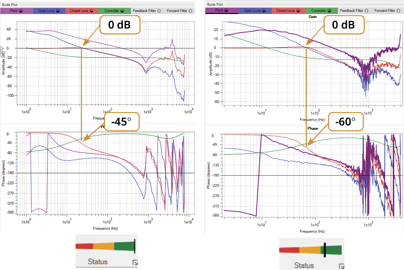
When there is 49 degrees controller phase lag, there is NO REDUCTION in error:

When there is 60 degrees controller phase lag, there is around a 20% increase in error:

Once Closed Loop drops below 0 dB, output of the control loop is not enough to compensate for error at 100%.
As the closed loop phase lag exceeds 60 dB a noticeable drop in performance, or increased instability, will occur due to excess increasing error.

Note: The 45 and 60 degrees of phase lag corresponds to the Closed Loop phase response of the system.
0 dB Crossover Phase Performance Zone
As higher performance is pushed by increasing the bandwidth, the closed loop phase lag increases. Keeping the resulting phase lag within a range of 40 to 60 degrees will maintain good stability. Pushing beyond 60 degrees phase lag invites stability issues. Falling below 40 degrees of phase lag leaves performance below an optimized state.


