AKD2G Support With MC_TouchProbe
These are tips related to using MC_TouchProbe with AKD2G drives![]() In electrical engineering, a drive is an electronic device to provide power to a motor or servo.
Control device for regulating the speed, torque and position of a motor.
A unit controlling a motor using the current and timing in its coils..
In electrical engineering, a drive is an electronic device to provide power to a motor or servo.
Control device for regulating the speed, torque and position of a motor.
A unit controlling a motor using the current and timing in its coils..
- AKD2G does not use CAP1 or CAP2 to provide the EtherCAT
 Ethernet ofr Control Automation Technology.
EtherCAT® is an open, high-performance Ethernet-based fieldbus system.
The development goal of EtherCAT is to apply Ethernet to automation applications which require short data update times (also called cycle times) with low communication jitter (for synchronization purposes) and low hardware costs. touch probes See Softscope - Probe item..
Ethernet ofr Control Automation Technology.
EtherCAT® is an open, high-performance Ethernet-based fieldbus system.
The development goal of EtherCAT is to apply Ethernet to automation applications which require short data update times (also called cycle times) with low communication jitter (for synchronization purposes) and low hardware costs. touch probes See Softscope - Probe item.. - AKD2G supports ETG6010 and DS402 for Touch Probe objects.
Two touch probes per axis are supported over EtherCAT with their own dedicated hardware in the drive.
Each touch probe can capture two positions, the position on the rising and the position of the falling edge of the trigger input.
These are the standards-compliant ETG6010 and DS402, EtherCAT / CANopen
CANopen® is a communication protocol and device profile specification for embedded systems used in automation for fieldbuses working in real time. objects AKD2G supports.Axis 1 Index
Zero pulse (zero signal) of a hardware pin such as digital input or feedback pin.Axis 2 Index
Name
Note
60B8h
68B8h
Touch probe function
A function calculates a result according to the current value of its inputs.
A function has no internal data and is not linked to declared instances. / control.60B9h
68B9h
Touch probe status.
60BAh
68BAh
Touch probe position 1 positive value.
AXIS#.PL.FB, Scaling same as axis
60BBh
68BBh
Touch probe position 1 negative value.
60BCh
68BCh
Touch probe position 2 positive value.
60BDh
68BDh
Touch probe position 2 negative value.
60D0H
68D0h
Touch probe source.
- AKD2G supports ETG6010 and DS402 for Touch Probe objects.
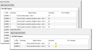
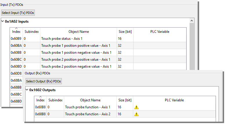
- The KAS-IDE Kollmorgen Automation Suite - Integrated Development Environment pre-populates these PDOs with the required Touch probe objects by default.
- Rx PDO Process Data Opjects - A type of protocol frame used in some fieldbuses. A PDO contains one or more object dictionary entries, which define the application data transferred between devices. 0x1602 with the required Touch Probe control objects.
- Tx PDO 0x1A02 with the required Touch Probe status and position value objects.
- Rx PDO
- The Trigger input source is set by sending an SDO command.
- Axis1:
0x60D0 sub Index 1 for Touch Probe 1 Source.
0x60D0 sub Index 2 for Touch Probe 2 Source.
- Axis2:
0x68D0 sub Index 1 for Touch Probe 1 Source.
0x68D0 sub Index 2 for Touch Probe 2 Source.
- Axis1:
- 6#D0h, Touch Probe Source.
This table shows how AKD2G signals are mapped to the touch probe source entry in the object dictionary.- A few sources appear in both the standard and the manufacture ranges to provide some consistency.
- When X22 is not fitted options -21 and -22 are not valid.
- When X23 is not fitted options -23 to -26 are not valid.
|
DS402 & ETG6010 Values |
Text from Standard |
AKD2G Values for 6#D0h |
Equivalent CAP#.TRIGGER |
AKD2G Note |
|---|---|---|---|---|
|
-32768 to -1 |
Manufacturer specific |
-41 to -42 |
41 to 42 |
Z pulse |
|
-31 to -35 |
31 to 35 |
Z pulse for Feedback 1 to 5. FB1, 2, 4, and 5 do not support Z pulses; these are not shown. When we support SFA on FB 1 and 2 then Z pulse may be possible. X23 is optional so if not fitted then -33 is not valid. |
||
|
-21 to -26 |
21 to 26 |
DIO1 to DIO6 |
||
|
-1 to -12 |
1 to 12 |
DIN1 to DIN12 When X22 is not fitted options -9 to -12 are not valid. |
||
|
0 |
Reserved |
|
|
Not valid. |
|
1 |
Digital Input 1 (Touch Probe input) |
1 |
1 |
DIN1. Fast Opto |
|
2 |
Digital Input 2 (Touch Probe input) |
2 |
2 |
DIN2. Fast Opto |
|
3 |
Digital Input 3 (Touch Probe input) |
|
|
Not valid. |
|
4 |
Digital Input 4 (Touch Probe input) |
|
|
Not valid. |
|
5 |
Hardware zero pulse |
5 |
41 for Axis 1 42 for Axis 2 |
Valid if PL.FBSOURCE is using a feedback that supports a Z pulse. |
|
6 |
Software zero pulse encoder |
|
|
Not valid. |
|
7 to 32767 |
Reserved |
|
|
Not valid. |


