Coordinated Motion - 3-Axis (3D) Template
This project template controls three axes in coordinated motion (PLCOpenAxis1, PLCOpenAxis2, and PLCOpenAxis3).
- It demonstrates how to use 3D coordinated motion, transitions, blending
 A way that consecutive function blocks cooperate in the transition from the first to the next. and a homing The homing procedure allows, based on a position measurement, to set a position offset to the motor to ensure it is physically at the home position. cycle with PLCopen A vendor -and product- independent worldwide association active in Industrial Control and aiming at standardizing PLC file formats based on XML. axes.
 - The path Set of continuous positions and orientation information in multi-dimensional space.
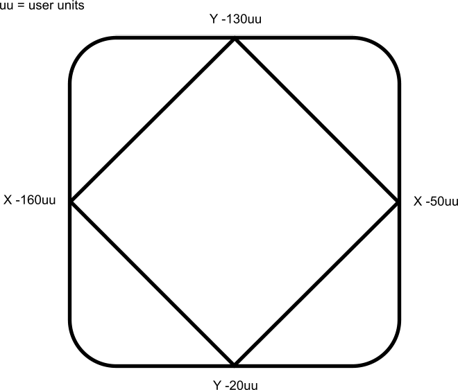
Geometrical description of a space curve that the TCP of an axesgroup moves along. follows a square and diamond pattern on a plane which is rotated ~12.5 degrees about the Y axis with the center of rotation located at Z=30 X=-160.
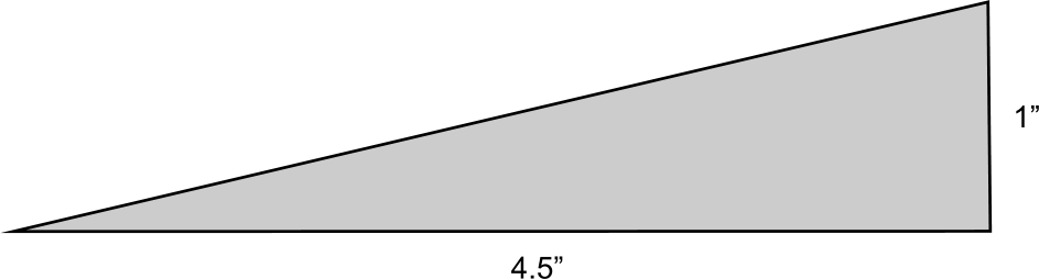
This is the pattern and the platform for the plane:
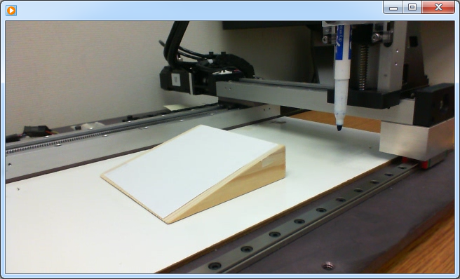
This video illustrates the motion.
Click the image to open the video in its own window.
-
-
This program
The act of performing a sequence of instructions or commands. is designed to run on the 3-Axis Demonstration machine The complete assembly of all connected parts or devices, of which at least one is movable. shown in the video.
It uses the machine’s physical end-limit switches for the homing sequence.
To run this program on different hardware, press the Sim Mode button on the Control Panel.
This causes the program to execute in simulator mode and bypasses the homing sequence.
The axis scaling parameters (entered in the PLCopen Axis Data dialogs) may need to be changed to accommodate the different hardware.
PLC Programs
The Coordinated Motion 3-Axis template has a Sequential Function![]() A function calculates a result according to the current value of its inputs.
A function has no internal data and is not linked to declared instances. Chart (SFC
A function calculates a result according to the current value of its inputs.
A function has no internal data and is not linked to declared instances. Chart (SFC![]() Sequential function chart - It can be used to program processes that can be split into steps.
The main components of SFC are:
- Steps with associated actions.
- Transitions with associated logic conditions.
- Directed links between steps and transitions.) program containing both Structured Text (ST
Sequential function chart - It can be used to program processes that can be split into steps.
The main components of SFC are:
- Steps with associated actions.
- Transitions with associated logic conditions.
- Directed links between steps and transitions.) program containing both Structured Text (ST![]() Structured text - A high-level language that is block structured and syntactically resembles Pascal.) and Free Form Ladder Diagram (FFLD) code.
Structured text - A high-level language that is block structured and syntactically resembles Pascal.) and Free Form Ladder Diagram (FFLD) code.
- Steps 1 to 5 of the SFC program create and initialize the axes and the coordinated motion axes group.
- Step 6 specifies the coordinates of the square and diamond pattern.
- These coordinates are then rotated about the Y-axis.
- Step 7 monitors the Control Panel and performs two main functions.
- The first function is to reference the axes to establish a home position Position means a point in space which is described by different coordinates.
Depending on the used system and transformation it can consist of a maximum of six dimensions (coordinates).This means three Cartesian coordinates in space and coordinates for the orientation.
In ACS there can be even more than six coordinates.
If the same position is described in different coordinate systems the values of the coordinates are different..
- The second function is to perform the 3-axis coordinated motion moves of the square diamond pattern.
- The first function is to reference the axes to establish a home position
This program provides examples of coordinated motion linear moves, transitions, blending, and a homing cycle.
Motion Pattern Procedure
- Download and start the application.
- Press the Enable Enable signal for the drive, Hardware-Enable with 24V signal to X8, Software-Enable command by setup Software, fieldbus or permanently set.
Both are required for enabling the drive. button to enable the axes and the axes group.
- After the Ready light is on:
- If working with the 3-Axis Demonstration machine, press the Home button to reference the axes and move them to their home position.
- If working with other hardware, press the Sim Mode button.
- After the Ready and Homed lights are on, turn the Cycle Start switch to 1.
The axes begin moving in the programmed pattern.
Control Panel
|
Image # |
Description |
GUI |
|---|---|---|
|
|
Used to change the coordinated motion feedrate from 0% to 200%. |
|
|
|
Displays the axis positions. |
|
|
|
Ready indicator light. Ready indicates:
|
|
|
|
Homed indicator light. Homed indicates:
|
|
|
|
Simulation Mode indicator light. Sim Mode indicates:
|
|
|
|
Begins the coordinated motion pattern. Ready and Homed lights must both be on to execute motion. |
|
|
|
Causes an Emergency Stop for all axes.
|
|
|
|
|
|
|
|
Disables the axes or axes group. The axes must be at a standstill to disable the group. |
|
|
|
Enables the axes and the axes group. This turns on the Ready light. |
|
|
|
Starts a homing function.
|
|
|
|
Sim Mode bypasses the homing function. This mode can be used when running on a simulator or when the hardware reference switches
|


