AKT2G-AC-FAN-001
Fan cartridge for EtherCAT and Bus Terminals
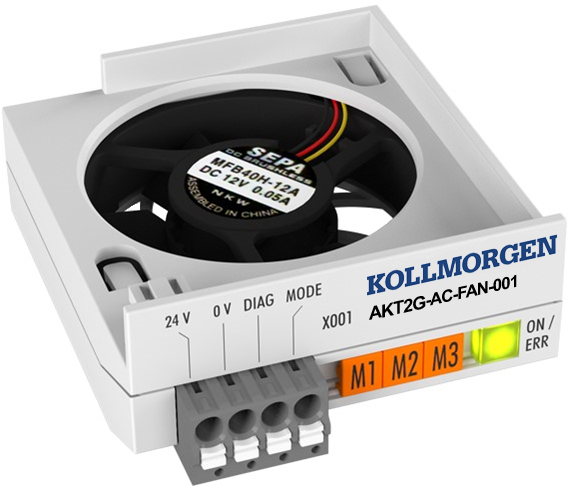
The AKT2G-AC-FAN-001 fan cartridge is used for forced ventilation within the terminal housing and ensures better heat dissipation from the housing.
- It extends the thermal operating range of EtherCAT Terminals (AKT2G-xxx) and K-Bus Terminals (AKT-xxx) and offers a wide range of new application options.
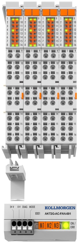
- The cartridge is installed on the underside of the terminal segment and covers a width of four standard terminals (4 x 12mm).
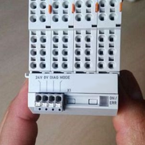
- It consists of the fan, an installation plate, a terminal strip (24VDC, 0VDC, diag, mode) and a bracket for fixation on different terminal housings.
Technical Data
|
Technical Data |
AKT2G-AC-FAN-001 |
|---|---|
|
Approval |
CE, UL CE, FCC, KCC CE, cULuscULus |
|
Current Consumption Power from Contacts
Current consumption (at 24V operating voltage) |
ca. 45mA |
|
Diagnostics, max. output current |
Fan fault, 15 mA. |
|
Dimensions (W x H x D) |
47mm x 22mm x 55mm |
|
EMC Immunity / Emission |
Conforms to EN 61000-6-2 / EN 61000-6-4. |
|
Life Span |
MTBF typ. = 280,000 h @ 20°C |
|
Nominal Voltage |
24 VDC (-15 %/+20 %) |
|
Number of channels |
1 fan |
|
Operating / Storage Temperature |
|
|
Operating Modes |
temperature-controlled, full speed, frequency controlled |
|
Protect. class / installation pos. |
IP20 |
|
Relative Humidity |
95%, no condensation. |
|
Rotational Frequency Fan |
|
|
Special Features |
Increased performance and extended temperature range for various terminals. |
|
Vibration / Shock Resistance |
Conforms to EN 60068-2-6 / EN 60068-2-27/29. |
|
Weight |
32g (including bracket) |
Mounting and Demounting
The AKT2G-AC-FAN-001 fan cartridge is snapped onto a 48-mm wide terminal group of Kollmorgen standard or high density (HD) terminals using the "8-channel/16-channel fan cartridge holder" supplied as an accessory.
The width of the individual terminals may be 12mm (single width) or 24mm (double width) or a combination of both.
The mounting of the AKT2G-AC-FAN-001 is described below by way of an example.
Mounting
-
-
Risk of injury through electric shock and damage to the device!
Bring the Bus Terminals system into a safe, de-energized state before starting mounting, disassembly or wiring of the Bus Terminals.
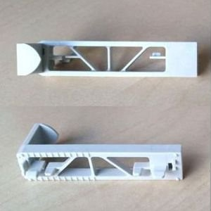
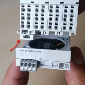
- Assemble the terminals to be ventilated into a group with a width of 48mm and snap the holder on the left in the lower ventilation cut-outs of the first terminal to be ventilated, as shown in Figure 1: "Engaging the holder for the fan cartridge".
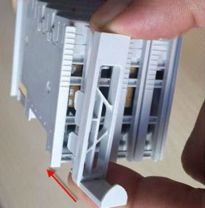
Figure 1: Engaging the holder for the fan cartridge
The holder is correctly engaged when a clear click sound is heard.
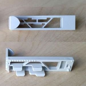
 Correctly engaged holder, front view
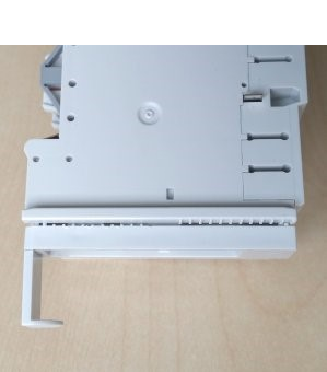 Correctly engaged holder, side view
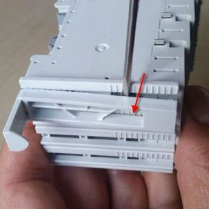
 - Push the fan cartridge onto the holder as shown in figure Attaching the fan cartridge. The holding tab and the recess (see figure Push fan cartridge with recess over holding tab) on the fan cartridge fit each other and close flush in a downward direction.
- Make sure that the latching tab is pushed into the groove until a click noise is heard as in "AKT2G-AC-FAN-001". The fan cartridge is now correctly attached.
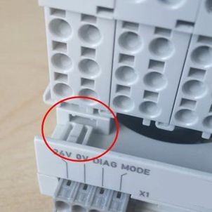
Figure 2: Push latching tab into groove
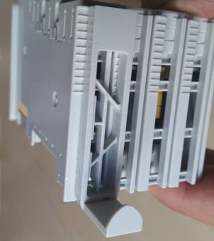
 Correctly attached fan cartridge, front view
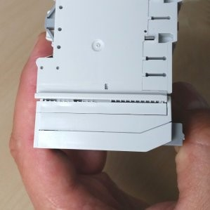 Correctly attached fan cartridge, side view
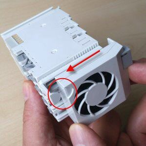
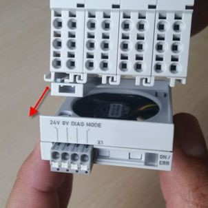
Removal
- To dismantle, pull the fan cartridge off the terminal group in the direction of the arrow (see the following figure).
- To detach the holder from the terminal, place a screwdriver between the terminal and holder (see the following figure) and carefully lever until the holder releases.
-
-
Clearance of the fan cartridge module
When installing terminals with mounted fan cartridge module ensure that an adequate spacing (> 35 mm) is maintained between other components above and below the terminals (incl. fan cartridge) in order to guarantee a flawless operation of the fan cartridge and adequate ventilation of the terminals.
LED Display and Connection
Figure 5: AKT2G-AC-FAN-001 LED
Diagnosis LED
|
LED |
Display |
||
|---|---|---|---|
|
On |
Off |
No power supply. |
|
|
Green |
On |
|
|
|
Flashing |
|
||
|
Red |
Error / fan malfunction. |
||
Connection
| Designation | Meaning |
|---|---|
| 24 V | +24 V power supply |
| 0 V | 0 V power supply |
| Mode |
Input speed regulation via external voltage
|
| Diag | Output diagnosis (max.
output current 15 mA)
|
Basic Function Principles and Commissioning
Area of application
The AKT2G-AC-FAN-001 fan cartridge is delivered ready to operate. No adjustments need to be made to the device.
A typical application of the fan module is extension of the performance range of the terminals through forced cooling. This enables the AKT2G-SM-L15-000 EtherCAT servo terminal to operate with higher output current so that the performance is on a par with the AKT2G-SM-L50-000 with the benefit of a 50% smaller footprint.
A further application is extension of the operating temperature range of the terminals. Depending on the technical specification, the fan module enables the terminals to operate at temperatures of up to 70 °C. The exact terminal-specific information for this application can be found in the documentation for the respective terminals.
Commissioning
- Connect the AKT2G-AC-FAN-001 fan cartridge according to the instructions in the section LED Display and Connection.
- The fan can be operated in three different modes:
- Demand-based control via an integrated temperature sensor (default, only power supply required)
- The fan cartridge starts operating at approx. 40 °C (2.700 U/min) and increases the speed stepwise with increasing temperature
- From approx. 55 °C the fan reaches the full speed ( ̴5.500 U/min)
- If the temperature decreases below approx. 35 °C, the fan cartridge switches off
- Continuous operation at full load (in addition to the power supply a high signal is applied at the mode pin.)
- Frequency controlled by an externally applied frequency (1 – 9 Hz) at the Mode pin, which is converted internally in steps from 2,700 rpm to max. ~5,500 rpm. A digital output terminal, for example, can be used as an external source. The measurement of the internal terminal temperature is used as reference for speed control of the fan via the frequency.
- Demand-based control via an integrated temperature sensor (default, only power supply required)
- In case of error there is a low signal on the "Diag" output and the LED display lights up red.