AKT2G-ENC-180-000

1-channel incremental encoder interfaceClosed Position signaling by 2 signals with 90° phase difference (i.e., quadrature) is no absolute position output., 32 bit

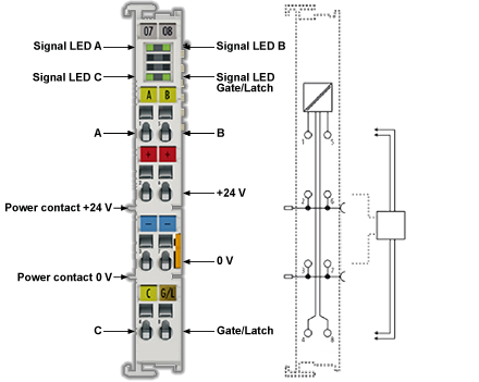
Incremental Encoder Interface AKT2G-ENC-180

The AKT2G-ENC-180 EtherCATClosed Ethernet ofr Control Automation Technology. EtherCAT® is an open, high-performance Ethernet-based fieldbus system. The development goal of EtherCAT is to apply Ethernet to automation applications which require short data update times (also called cycle times) with low communication jitter (for synchronization purposes) and low hardware costs. Terminal is an interface with 24 V inputs for the directClosed The orientation components of a vector in space. connection of incremental encodersClosed The incremental encoder is simpler in design than the absolute encoder. It consists of two tracks and two sensors whose outputs are called channels A and B. As the shaft rotates, pulse trains occur on these channels at a frequency proportional to the shaft speed. The phase relationship between the signals yields the direction of rotation. AKA: Relative encoder.. A 32 bit counter with a quadrature decoder and a 32 bit latchClosed The control word is used to activate the drive's latch status machine. The latch control word is processed independently of the EtherCAT® bus cycle. The status word is used to return the drive's latch status. for the zero pulseClosed Output once per turn from incremental encoders, used to zero the machine. can be read, set or enabledClosed Enable signal for the drive, Hardware-Enable with 24V signal to X8, Software-Enable command by setup Software, fieldbus or permanently set. Both are required for enabling the drive..

The measurement of periodClosed Motor systems having a reciprocating or oscillating motor that operates synchronously with the periodicity of the source which supplies the electrical energy. The period of execution of a pipe is the time spent between two successive computations of set values for the same pipe. The period of execution of a pipe is specified by the PERIOD parameter of the input pipe block. and frequency is possible. The gate input allows the locking of the counter, selectively with a high or low level. The latch input is similarly configurable and evaluates high or low levels.

The AKT2G-ENC-180 supports distributed clocksClosed Clock signal., i.e. the input data can be synchronouslyClosed Combines an axis or axes group (as slave) with an axis as master. The slave executes its path with synchronization to the progress of the master. This is linked to a one dimension source for synchronization. acquired with other data that are similarly connected, distributed to distributed clock terminals. The universal system accuracyClosed Accuracy is the distance between the actual position of a mechanical system and the expected position. It is typically specified in microns or arcsec per given travel for a deviation of ±3 (sigma). is around < 100 ns.

With a moving axis, the micro-increment functionalityClosed A function calculates a result according to the current value of its inputs. A function has no internal data and is not linked to declared instances. offers 256 times higher axis positionClosed Position means a point in space which is described by different coordinates. Depending on the used system and transformation it can consist of a maximum of six dimensions (coordinates).This means three Cartesian coordinates in space and coordinates for the orientation. In ACS there can be even more than six coordinates. If the same position is described in different coordinate systems the values of the coordinates are different. resolutionClosed The resolution is the smallest possible movement that can be achieved by a system. It can be defined at the electronics, encoder and mechanics level. The distance a stage can be commanded to move in a single step. For servo systems, the basic increment produced by its optical encoder, or any other feedback device. than physically provided by the encoderClosed Generates an output signal directly proportional to the movement of the motor shaft. This signal is fed into the control circuitry to control the shaft position and speed. The most common types are: Incremental/Serial encoders, Hall effect sensors, Resolvers, Tachometer Generators See: Optical encoders..

The AKT2G-ENC-180 can also be used as a single-channel 32/16 bit counter on channel A, in which case the signal level on channel B defines the countClosed Internal count pulses, 1 pulse = 1/2^20turn. direction.

Related Topics: Map Input and Output to Variables

AKT2G-ENC-180 Technical Data

Technical Data

AKT2G-ENC-180-000

SensorClosed A type of transducer that converts one type of energy into another for various purposes including measurement or information transfer. inputs 1
Encoder connection A, B, C, gate/latch input, 24 V
Encoder operating voltage 24 V
Signal voltage "0" (inputs A, B, C, gate/latch) 0 V .. 5 V (EN 61131-2, type 1)
Signal voltage "1" (inputs A, B, C, gate/latch) 15 V .. 30 V (EN 61131-2, type 1)
Counter 1 x 32/16-bit binary, switchable
Limit frequency max. 400,000 increments/s with 4-fold evaluation), corresponds to 100 kHz
Quadrature decoder 4-fold evaluation
TimestampClosed A sequence of characters, denoting the date and/or time at which a certain event occurred. resolution 1 ns
Timestamp accuracy 100 ns
Commands Read, set, latch, gate function
Power supply for electronic via the E-Bus
Distributed Clocks yes
Supply voltage 24 VDC (-15 %/+20 %)
Current consumption from the E-bus typ. 130 mA
Current consumption from the power contacts 0.1 A (excluding sensor load current)
Electrical isolation 500 V (E-bus/field voltage)
Supports NoCoeStorage function yes
Weight approx. 50 g
Permissible ambient temperature range during operation -25 °C ... +60 °C (extended temperature range)
Permissible ambient temperature range during storage -40 °C ... +85 °C
Permissible relative humidity 95%, no condensation
Dimensions (W x H x D) approx. 15 mm x 100 mm x 70 mm (width aligned: 12 mm)
Mounting on 35 mm mounting rail conforms to EN 60715
Vibration/shock resistance according to EN 60068-2-6/EN 60068-2-27, see also Installation instructions for terminals with increased mechanical load capacity
EMC immunity/emission conforms to EN 61000-6-2 / EN 61000-6-4
Protection class IP20
Installation position variable
Approval CE, ATEX, cULus