AKT2G-SM-L50 General Connection Examples
-
-
Risk of injury through electric shock and damage to the device!
Bring the Bus Terminal system into a safe, de-energized state before starting mounting, disassembly or wiring of the Bus Terminals.
-
-
Connect the motor
 An actuator focused to a movement, converting electrical energy in a force or torque. strands correctly!
Connect the windings of a motor strand only to the terminal points of the same output driver
In computing and electronics, a driver is a software component allowing higher-level computer programs to interact with a computer hardware device.
A driver typically communicates with the device through the computer bus or communications subsystem to which the hardware is connected. of the stepper motor terminal, e.g.:- one motor strand to terminal points A1 and A2,
- the other motor strand to terminal points B1 and B2.
Connecting a motor strand to the terminal points of different output drivers (e.g. to A1 and B1) can lead to destruction of the output drivers of stepper motor terminal!
-
-
Use a brake chopper terminal (Global search and replace: AKT2G-BRC-000-000) for short deceleration ramps
The gradual acceleration and deceleration of a stepping motor.
This is essential if performance beyond the start/stop range is required.
The slope of the ramp is a function of screw pitch, load, drive voltage and design, and motor.!Very short deceleration ramps may lead to temporarily increased feedback. In this case the terminal would report an error. In order to avoid this, a brake chopper terminal AKT2G-BRC-000-000 should be connected in parallel to the power supply for the motor so that any energy being fed back is absorbed.
-
-
Fuse protection of the supply voltage
The electrical protection of the load voltage must be selected in such a way that the maximum flowing current is limited to 3 times the rated current (max. 1 second)!
Connection types
The AKT2G-SM-L50 Stepper Motor terminal has bipolar output stages and can control bipolar and unipolar motors.
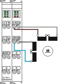
Bipolar motors
|
|
|
Figure 1: Bipolar control (serial) of a bipolar motor |
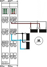
Figure 2: Bipolar control (parallel) of a bipolar motor |
Unipolar Motors
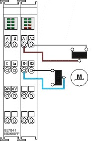
Figure 3: Bipolar control with only one half of each winding is controlled
Encoder
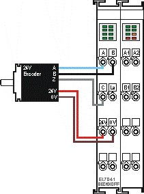
Figure 4: The encoder is supplied from the power contacts via terminal points 3 (+24 V) and 7 (0 V).


