Safety Terminal Reaction Times
The safety terminals form a modular safety system that exchanges safety-oriented data via the Safety-over-EtherCAT![]() Ethernet ofr Control Automation Technology.
EtherCAT® is an open, high-performance Ethernet-based fieldbus system.
The development goal of EtherCAT is to apply Ethernet to automation applications which require short data update times (also called cycle times) with low communication jitter (for synchronization purposes) and low hardware costs. protocol. This topic is intended to help you determine the system's reaction time from the change of signal at the sensor
Ethernet ofr Control Automation Technology.
EtherCAT® is an open, high-performance Ethernet-based fieldbus system.
The development goal of EtherCAT is to apply Ethernet to automation applications which require short data update times (also called cycle times) with low communication jitter (for synchronization purposes) and low hardware costs. protocol. This topic is intended to help you determine the system's reaction time from the change of signal at the sensor![]() A type of transducer that converts one type of energy into another for various purposes including measurement or information transfer. to the reaction at the actuator
A type of transducer that converts one type of energy into another for various purposes including measurement or information transfer. to the reaction at the actuator![]() A mechanical device for moving or controlling a mechanism or system.
An actuator is typically a mechanical device which transforms an input signal (usually an electrical signal) into motion.
The actuator is usually a physical mechanism but it can also refer to an artificial agent or intelligent agent.
Virtual Instrumentation: Actuators and sensors are the hardware complements of virtual instruments.
Computer programs of virtual instruments use actuators to act upon real world objects..
A mechanical device for moving or controlling a mechanism or system.
An actuator is typically a mechanical device which transforms an input signal (usually an electrical signal) into motion.
The actuator is usually a physical mechanism but it can also refer to an artificial agent or intelligent agent.
Virtual Instrumentation: Actuators and sensors are the hardware complements of virtual instruments.
Computer programs of virtual instruments use actuators to act upon real world objects..
Typical Reaction Time
The typical reaction time is the time that is required to transmit information from the sensor to the actuator, if the overall system is working without error in normal operation.
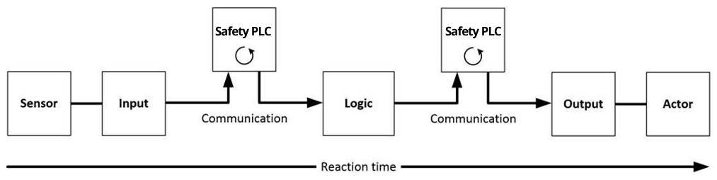
Figure 1: Typical reaction time
| Definition | Description |
|---|---|
|
RTSensor |
Reaction time of the sensor until the signal is provided at the interface. Typically supplied by the sensor manufacturer. |
|
RTInput |
Reaction time of the safe input, such as AKT2G-SDI-004. This time can be found in the technical data. In the case of the AKT2G-SDI-004 it is 4 ms. |
|
RTComm |
Reaction time of the
communication This is typically 3x the EtherCAT cycle time, because new data
can only be sent in a new Safety-over-EtherCAT telegram. These times depend
directly |
|
RTLogic |
Reaction time of the logic terminal. This is the cycle time of the safety PLC, depending on the size of the safety project. |
|
RTOutput |
Reaction time of the output terminal. This typically lies within the range of 2 to 3 ms. |
|
RTActor |
Reaction time of the actuator. This information is typically supplied by the actuator manufacturer |
|
WDComm |
Watchdog time of the communication |
This results in the following equation for the typical reaction time:

with, for example

Worst-Case Reaction Time
The worst case reaction time is the maximum time required to switch off the actuator in the case of an error.
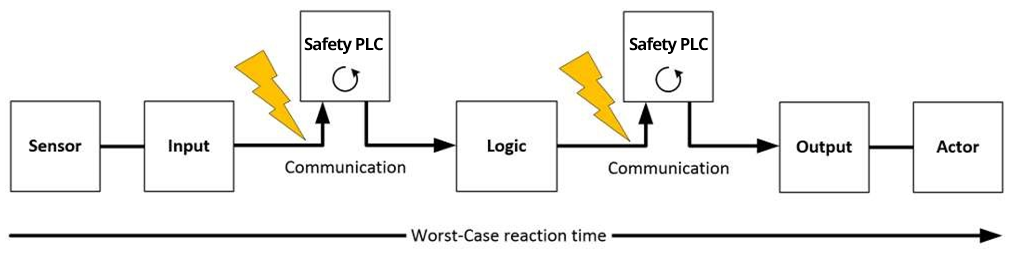
Figure 2: Worst-case reaction time
This assumes that a signal change occurs at the sensor and is transmitted to the input. A communication error occurs at precisely the moment when the signal is to be transferred to the communication interface. This is detected by the logic following the watchdog time of the communication link. This information should then be transferred to the output, but a further communication error occurs here. This error is detected at the output following the expiry of the watchdog time and leads to the switch-off.
This results in the following equation for the worst-case reaction:

with, for example


