About Stepper Motors
Stepper motors![]() An actuator focused to a movement, converting electrical energy in a force or torque. are electric motors and are comparable with synchronous
An actuator focused to a movement, converting electrical energy in a force or torque. are electric motors and are comparable with synchronous![]() Combines an axis or axes group (as slave) with an axis as master. The slave executes its path with synchronization to the progress of the master. This is linked to a one dimension source for synchronization. motors. The rotor is designed as a permanent magnet, while the stator consists of a coil package. The frequency of the stator rotary field is always in a fixed ratio relative to the rotor speed
Combines an axis or axes group (as slave) with an axis as master. The slave executes its path with synchronization to the progress of the master. This is linked to a one dimension source for synchronization. motors. The rotor is designed as a permanent magnet, while the stator consists of a coil package. The frequency of the stator rotary field is always in a fixed ratio relative to the rotor speed![]() Speed is the absolute value of the velocity without direction.. In contrast to synchronous motors, stepper motors have a large number of pole pairs. In a minimum control configuration, the stepper motor is moved from pole to pole, or from step to step.
Speed is the absolute value of the velocity without direction.. In contrast to synchronous motors, stepper motors have a large number of pole pairs. In a minimum control configuration, the stepper motor is moved from pole to pole, or from step to step.
Stepper motors have been around for many years. They are robust, easy to control, and provide high torque![]() The tendency of a force to rotate an object about an axis.
A force is a push or a pull; a torque is a twist.. In many applications, the step counting
The tendency of a force to rotate an object about an axis.
A force is a push or a pull; a torque is a twist.. In many applications, the step counting![]() Internal count pulses, 1 pulse = 1/2^20turn. facility saves expensive feedback systems. Even with the increasingly widespread use of synchronous servomotors, stepper motors are by no means "getting long in the tooth". They are considered to represent mature technology and continue to be developed further in order to reduce costs and physical size, increase torque and improve reliability. For a standard stepper motor with 200 full steps, the best possible positioning
Internal count pulses, 1 pulse = 1/2^20turn. facility saves expensive feedback systems. Even with the increasingly widespread use of synchronous servomotors, stepper motors are by no means "getting long in the tooth". They are considered to represent mature technology and continue to be developed further in order to reduce costs and physical size, increase torque and improve reliability. For a standard stepper motor with 200 full steps, the best possible positioning![]() Position means a point in space which is described by different coordinates.
Depending on the used system and transformation it can consist of a maximum of six dimensions (coordinates).This means three Cartesian coordinates in space and coordinates for the orientation.
In ACS there can be even more than six coordinates.
If the same position is described in different coordinate systems the values of the coordinates are different. accuracy
Position means a point in space which is described by different coordinates.
Depending on the used system and transformation it can consist of a maximum of six dimensions (coordinates).This means three Cartesian coordinates in space and coordinates for the orientation.
In ACS there can be even more than six coordinates.
If the same position is described in different coordinate systems the values of the coordinates are different. accuracy![]() Accuracy is the distance between the actual position of a mechanical system and the expected position.
It is typically specified in microns or arcsec per given travel for a deviation of ±3 (sigma). is approx. 1.8°.
Accuracy is the distance between the actual position of a mechanical system and the expected position.
It is typically specified in microns or arcsec per given travel for a deviation of ±3 (sigma). is approx. 1.8°.
Today, the most widely used type in industry is the hybrid stepper motor type. In this type of motor the rotor consists of a toothed iron core with one or a few permanent magnets in the rotor core. The rotor is designed such that the polarity of successive teeth is inverse. This enables![]() Enable signal for the drive, Hardware-Enable with 24V signal to X8, Software-Enable command by setup Software, fieldbus or permanently set.
Both are required for enabling the drive. the production of motors with a high number of steps, which is essential for positioning accuracy, combined with a relatively high torque. The electrical behavior of such a hybrid stepper motor is comparable with a multi-pole synchronous servomotor. However, thanks to the synchronous toothing of stator and rotor, hybrid stepper motors offer a significantly higher cogging torque.
Enable signal for the drive, Hardware-Enable with 24V signal to X8, Software-Enable command by setup Software, fieldbus or permanently set.
Both are required for enabling the drive. the production of motors with a high number of steps, which is essential for positioning accuracy, combined with a relatively high torque. The electrical behavior of such a hybrid stepper motor is comparable with a multi-pole synchronous servomotor. However, thanks to the synchronous toothing of stator and rotor, hybrid stepper motors offer a significantly higher cogging torque.
Hybrid stepper motors with two or more phases are available on the market. Since the terminals described here are designed for two-phase motors, the description focuses on the two-phase type, with the phases referred as A and B in this documentation.
Stepper Motor Parameters
- Mechanical system
- Irrespective of the drive
 In electrical engineering, a drive is an electronic device to provide power to a motor or servo.
Control device for regulating the speed, torque and position of a motor.
A unit controlling a motor using the current and timing in its coils. and the stepper motor itself, the configuration of the mechanism attached to the motor shaft has significant influence on the achievable control quality.
In electrical engineering, a drive is an electronic device to provide power to a motor or servo.
Control device for regulating the speed, torque and position of a motor.
A unit controlling a motor using the current and timing in its coils. and the stepper motor itself, the configuration of the mechanism attached to the motor shaft has significant influence on the achievable control quality. - Natural resonances, load resonances, gear backlash The backlash is an error in positioning caused by the reversal of travel direction.
It is caused by a clearance between the elements of the mechanical system.
The backlash:
* Affects the bidirectional repeatability.
* Can be compensated by the position controller. (loose) and static friction have negative affect on the controllability of the drive system. This often requires "softer" controller parametrization, which in turn leads to a higher position lag in the system. Sliding friction can result in reduced efficiency (due to increased energy demand), but on the other hand it can have a positive effect on the control stability, due to its dampening effect.
- As a general rule, the "stiffer" the mechanics of a drive system, the easier it is to control, which is beneficial for achieving a small position lag in the drive system.
- Speed
- Stepper motors have low maximum speed, which is usually specified as a maximum step frequency.
- Number of phases
- Motors with 2 to 5 phases are common. The AKT2G-IO-SM-Lxx EtherCAT Ethernet ofr Control Automation Technology.
EtherCAT® is an open, high-performance Ethernet-based fieldbus system.
The development goal of EtherCAT is to apply Ethernet to automation applications which require short data update times (also called cycle times) with low communication jitter (for synchronization purposes) and low hardware costs. Terminals support 2-phase motors. 4-phase motors are basically 2-phase motors with separate winding ends. They can be connected directly The orientation components of a vector in space. to the EtherCAT Terminal.
- Torque
- Refers to the maximum motor torque at different speeds. This parameter is usually represented by a characteristic curve. Stepper motors have comparatively high torque in the lower speed range. In many applications, this enables them to be used directly without gearing. Compared with other motors, stepper motors can quite easily provide a holding moment of the same order of magnitude as the torque.
- Cogging torque
- In many cases the stepper motors design results in high cogging torque, which can lead to relatively strong natural resonance in a motor- and load-dependent speed range. In relation to the cogging torque, increased inertia often leads to a less strong resonance and smoother operation.
- Mass moment of inertia
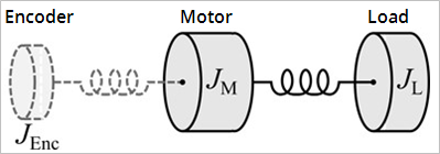
- In standard mode, the key parameter of the mechanical system is the mass moment of inertia JΣ. It is essentially composed of the mass moment of inertia of the stepper motor rotor JM and the mass moment of inertia of the connected load JL. The friction moment Jfric and the moment of inertia of the encoder Generates an output signal directly proportional to the movement of the motor shaft.
This signal is fed into the control circuitry to control the shaft position and speed.
The most common types are: Incremental/Serial encoders, Hall effect sensors, Resolvers, Tachometer Generators
See: Optical encoders. JEnc can be neglected in a first approximation.
JƩ ≈ JM + JL- The ratio between the load torque and the motor torque is defined by the constant kJ.
kJ ≈ JL / JM-
-
Figure 1: Simplified representation of the mass moments of inertia
- As a first approximation, the coupling of the individual masses over the rotor shaft can be modelled as twomass oscillator. The resonance frequency between the motor and the encoder lies in a relatively high frequency range, which is usually not relevant for stepper motor drives and is suppressed within the drive by low-pass filtering. The resonance frequency between the motor and the load is frequently in the range between 20 and 500 Hz. It is therefore often in the operating range of the drive control. Design measures to reduce the influence of the load resonance include a small load ratio kJ and a rigid coupling of the motor shaft to the connected load.
- Resonance
- At certain speeds, stepper motors run less smoothly. This phenomenon is particularly pronounced when the motor runs without coupled load, in which case it may even stop (in standard mode). This is caused by resonance. A distinction can roughly be made between
-
- resonances in the lower frequency range up to approx. 250Hz; and
- resonances in the medium to upper frequency range.
- Resonances in the medium to upper frequency range essentially result from electrical parameters such as inductance The tendency of a motor coil to store energy in a magnetic field.
High speed stepping motor performance is inversely proportional to motor inductance. of the motor winding and supply line capacity. They can be controlled relatively easily through high pulsing When the step gets activated, the action is activated for a single execution, and possibly once again when the step is deactivated. of the control system.
- Resonances in the lower range essentially result from the mechanical motor parameters. Apart from their impact on smooth running, such resonances can lead to significant loss of torque, or even loss of step of the motor, and are therefore particularly undesirable.
- In principle, the stepper motor represents an oscillatory system (comparable to a mass/spring system), consisting of the moving rotor with a moment of inertia and a magnetic field that creates a restoring force that acts on the rotor. Moving and releasing the rotor creates a damped oscillation. If the control frequency corresponds to the resonance frequency, the oscillation is amplified, so that in the worst case the rotor will no longer follow the steps, but oscillate between two positions.
- Torque constant
- In the Extended Operation Modes the torque constant kT is used as an additional parameter for the mechanical controlled system. It indicates the ratio between the torque-forming motor current and the active torque at the shaft. However, since the field-oriented operating mode is not common for stepper motors, the torque constant is usually not listed in the motor data sheet.
Electrical system
- Nominal voltage, supply voltage and winding resistance
- Under steady-state conditions, the rated current at the rated voltage depends on the winding resistance. This voltage should not be confused with the supply voltage of the power output stage in the EtherCAT Terminal. The AKT2G-IO-SM-Lxx applies a controlled current to the motor winding. If the supply voltage falls below the nominal voltage, the power output stage can no longer apply the full current, resulting in a loss of torque. It is desirable to aim for systems with small winding resistance and high supply voltage in order to limit warming and achieve high torque at high speeds.
- Induced countervoltage
- Like servomotors, hybrid stepper motors induce a voltage ui [Vs/rad] in the stator winding of the motor, which is proportional to the speed. It is also referred to as Back Electromotive Force (BEMF). In conjunction with the DC link voltage (motor voltage), the induced countervoltage determines the physically achievable maximum speed of the motor.
- The ratio of the magnitude of the induced countervoltage and the motor speed varies depending on the design and is described via the voltage constant ke.
ui = ke·ωm- The motor parameter
ke [mV/(rad/s)]is required for step loss recognition without encoder and for sensorless control. - For stepper motors where the voltage constant is not specified in the data sheet, it can be relatively easily determined using a digital multimeter. To this end the motor to be measured must be operated (within the rated speed range) by an auxiliary motor via a coupling with constant speed. The motor phases of the motor to be measured must be open (not connected to the terminal or shorted). The multimeter can then be used to determine the RMS value of the induced countervoltage, and therefore the voltage constant, at one of the two open motor phases (A or B).
- Step angle
- The step angle indicates the angle traveled during each step. Typical values are 3.6°, 1.8° and 0.9°. This corresponds to 100, 200 and 400 steps per motor revolution. Together with the downstream transmission ratio, this value is a measure for the positioning accuracy. For technical reasons, the step angle cannot be reduced below a certain value. Positioning accuracy can only be improved further by mechanical means (transmission). An elegant solution for increasing the positioning accuracy is the microstepping A technique which, instead of switching phase currents in a stepping motor on and off, sinusoidally varies the current in the two windings.
This effectively increases the resolution from 200 steps per revolution to 2,000 (~10) or 10,000 (~50) microsteps per revolution. function A function calculates a result according to the current value of its inputs.
A function has no internal data and is not linked to declared instances. offered by the AKT2G-IO-SM-Lxx. It enables up to 64 intermediate steps. The smaller "artificial" step angle has a further positive effect: The drive can be operated at higher speed, yet with the same precision. The maximum speed is unchanged, despite the fact that the drive operates at the limit of mechanical resolution The resolution is the smallest possible movement that can be achieved by a system.
It can be defined at the electronics, encoder and mechanics level.
The distance a stage can be commanded to move in a single step.
For servo systems, the basic increment produced by its optical encoder, or any other feedback device..
- Winding resistance, Winding inductance
- The winding inductance and winding resistance of the stepper motor stator determine the electrical motor time constant
Te = L / R, which is a key parameter for current controller Regulates the difference between the current setpoint and the actual value to 0.
Output : power output voltage. configuration.
Specifying the Stepper Motor
- Determine the required positioning accuracy and hence the step resolution. The first task is to determine the maximum resolution that can be achieved. The resolution can be increased via mechanical gear reduction devices such as spindles, gearing or toothed racks. The 64-fold microstepping of the stepper motor terminals also has to be taken into account.
- Determine mass m and moment of inertia (J) of all parts to be moved
- Calculate the acceleration A change in velocity over time.
Because velocity is a vector, it can change in two ways: a change in magnitude and/or a change in direction.
In one dimension, acceleration is the rate at which something speeds up or slows down.
However, more generally, acceleration is a vector quantity expressing the change with time of the velocity both in magnitude and in direction.
See these Wikipedia articles for more information:
http://en.wikipedia.org/wiki/Velocity
http://en.wikipedia.org/wiki/Euclidean_vector
http://en.wikipedia.org/wiki/Rate_(mathematics) resulting from the temporal requirements of the moved mass.
- Calculate the forces from mass, moment of inertia, and the respective accelerations.
- Convert the forces and velocities For a group of axes this means: In ACS the velocities of the different axes. In MCS and PCS it provides the velocity of the TCP to the rotor axis, taking account of efficiencies, moments of friction and mechanical parameters such as gear ratio. It is often best to start the calculation from the last component, usually the load. Each further element transfers a force and velocity and leads to further forces or torques due to friction. During positioning, the sum of all forces and torques acts on the motor shaft. The result is a velocity/torque curve that the motor has to provide.
- Using the characteristic torque curve, select a motor that meets these minimum requirements. The moment of inertia of the motor has to be added to the complete drive. Verify your selection. In order to provide an adequate safety margin, the torque should be oversized by 20% to 30%. The optimisation is different if the acceleration is mainly required for the rotor inertia. In this case, the motor should be as small as possible.
- Test the motor under actual application conditions: Monitor the housing temperatures during continuous operation. If the test results do not confirm the calculations, check the assumed parameters and boundary conditions. It is important to also check side effects such as resonance, mechanical play, settings for the maximum operation frequency and the ramp The gradual acceleration and deceleration of a stepping motor.
This is essential if performance beyond the start/stop range is required.
The slope of the ramp is a function of screw pitch, load, drive voltage and design, and motor. slope.
- Different measures are available for optimising the performance of the drive: using lighter materials or hollow instead of solid body, reducing mechanical mass. The control system can also have significant influence on the behaviour of the drive. The Bus Terminal enables operation with different supply voltages. The characteristic torque curve can be extended by increasing the voltage. In this case, a current increase factor can supply a higher torque at the crucial moment, while a general reduction of the current can significantly reduce the motor temperature. For specific applications, it may be advisable to use a specially adapted motor winding.


