Standard Mode
Stepper motors![]() An actuator focused to a movement, converting electrical energy in a force or torque. were originally operated with very simple output stages, which were only able to switch the voltage of the motor phases separately (nowadays current control
An actuator focused to a movement, converting electrical energy in a force or torque. were originally operated with very simple output stages, which were only able to switch the voltage of the motor phases separately (nowadays current control![]() Regulates the difference between the current setpoint and the actual value to 0.
Output : power output voltage. takes place via PWM with pulse-width modulation as standard). Initially the motor phases there were controlled individually in turn. A switching sequence in the positive
Regulates the difference between the current setpoint and the actual value to 0.
Output : power output voltage. takes place via PWM with pulse-width modulation as standard). Initially the motor phases there were controlled individually in turn. A switching sequence in the positive![]() Position means a point in space which is described by different coordinates.
Depending on the used system and transformation it can consist of a maximum of six dimensions (coordinates).This means three Cartesian coordinates in space and coordinates for the orientation.
In ACS there can be even more than six coordinates.
If the same position is described in different coordinate systems the values of the coordinates are different. direction
Position means a point in space which is described by different coordinates.
Depending on the used system and transformation it can consist of a maximum of six dimensions (coordinates).This means three Cartesian coordinates in space and coordinates for the orientation.
In ACS there can be even more than six coordinates.
If the same position is described in different coordinate systems the values of the coordinates are different. direction![]() The orientation components of a vector in space. of rotation corresponds to the switching sequence (+A, +B, -A, -B). Sequential switching results in rather irregular operation in this mode. In order to make the operation smoother, so-called microstepping
The orientation components of a vector in space. of rotation corresponds to the switching sequence (+A, +B, -A, -B). Sequential switching results in rather irregular operation in this mode. In order to make the operation smoother, so-called microstepping![]() A technique which, instead of switching phase currents in a stepping motor on and off, sinusoidally varies the current in the two windings.
This effectively increases the resolution from 200 steps per revolution to 2,000 (~10) or 10,000 (~50) microsteps per revolution. was introduced later, in which the four set voltages were extended by intermediate values (e.g. from a stored sine table). These days, microstepping based on 64 steps is commonly used.
A technique which, instead of switching phase currents in a stepping motor on and off, sinusoidally varies the current in the two windings.
This effectively increases the resolution from 200 steps per revolution to 2,000 (~10) or 10,000 (~50) microsteps per revolution. was introduced later, in which the four set voltages were extended by intermediate values (e.g. from a stored sine table). These days, microstepping based on 64 steps is commonly used.
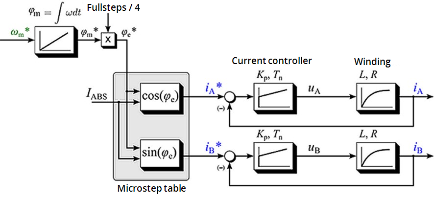
Figure 1: Control structure of a standard stepper motor drive
Neglecting the sampling resulting from the microstepping, the motor current I as function![]() A function calculates a result according to the current value of its inputs.
A function has no internal data and is not linked to declared instances. of the electrical angle φe and of the magnitude of the motor current IABS (when using a current controller) can be described as follows:
A function calculates a result according to the current value of its inputs.
A function has no internal data and is not linked to declared instances. of the electrical angle φe and of the magnitude of the motor current IABS (when using a current controller) can be described as follows:
I(φe) = IA + jIB = IABScos(φe) + jIABSsin(φe)
Represented by magnitude and angle:
I(φe) = IABS · ejφe
It follows that a rotation of the electrical angle φe is equivalent to four full steps. (A stepper motor with 200 full steps therefore has 50 pole pairs).
The shaft aligns itself if a constant current is set with no load at the motor shaft. Within a pole pairs the shaft points in the direction of the active stator field.
If an external load is applied to the motor shaft, the shaft is turned out of the field direction, resulting in a load angle (also referred to as angular displacement) (relative to an electric rotation of the angle φe). The load angle depends on the design of the stepper motor itself, the motor current and the torque![]() The tendency of a force to rotate an object about an axis.
A force is a push or a pull; a torque is a twist. acting on the shaft. The relationship is non-linear!
The tendency of a force to rotate an object about an axis.
A force is a push or a pull; a torque is a twist. acting on the shaft. The relationship is non-linear!
If the load angle exceeds a motor-dependent maximum value (i.e. if the maximum machine![]() The complete assembly of all connected parts or devices, of which at least one is movable. torque under these boundary conditions is exceeded), the load torque can no longer be maintained by the motor. If the shaft is turned further out of the rotary field, it "tips", resulting in one or more step losses. The "tip angle" may vary between motor types. Often, it lies between around 45° and 65°.
The complete assembly of all connected parts or devices, of which at least one is movable. torque under these boundary conditions is exceeded), the load torque can no longer be maintained by the motor. If the shaft is turned further out of the rotary field, it "tips", resulting in one or more step losses. The "tip angle" may vary between motor types. Often, it lies between around 45° and 65°.
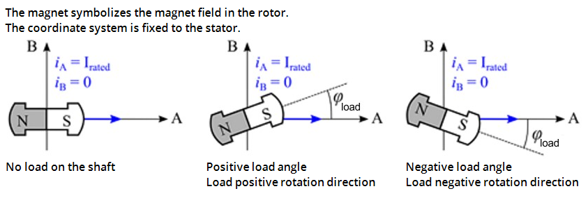
Figure 2: Behavior of the rotor under load
The load angle is of interest for the user, because it allows conclusions about the load on the shaft. It is measured by evaluating the induced countervoltage* and can be used to epitomize the drive![]() In electrical engineering, a drive is an electronic device to provide power to a motor or servo.
Control device for regulating the speed, torque and position of a motor.
A unit controlling a motor using the current and timing in its coils. system.
In electrical engineering, a drive is an electronic device to provide power to a motor or servo.
Control device for regulating the speed, torque and position of a motor.
A unit controlling a motor using the current and timing in its coils. system.


