 MC_MoveLinAbs

Description
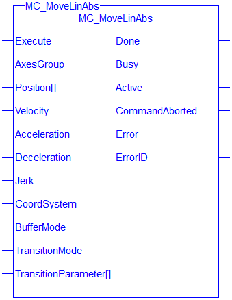
MC_MoveLinAbs commands interpolated linear movement on an axes group to the specified absolute positions in the coordinate system as specified by the 'CoordSystem' argument. The dimensionality of the move is determined by the number of axes mapped to the group.
-
-
- An error is returned if the group is in the GroupDisabled state.
- The maximum number of axes is set by the MaxNumberOfAxes input set in the MC_CreateAxesGrp function block.
- S-Curve motion is not currently supported. The Jerk
 In physics, jerk is the rate of change of acceleration; more precisely, the derivative of acceleration with respect to time input is currently ignored. S-Curve motion and the Jerk argument will be supported in a future release. .
When all motion has completed successfully, the state of the axes group goes to GroupStandby.
Related Functions
MC_MoveLinRel, MC_ErrorDescription
Coordinated Motion, the top-level topic for Coordinated Motion.
Arguments
Input
| Execute |
Description |
On the rising edge |
| Data Type | BOOL | |
| Range | 0, 1 | |
| Unit | n/a | |
| Default | — | |
| AxesGroup |
Description |
The axis group that will perform the linear absolute move |
| Data Type | AXIS_GROUP_REF | |
| Range | n/a | |
| Unit | n/a | |
| Default | — | |
| Position[] |
Description |
Array of absolute end positions for each axis in the group. |
| Data Type | LREAL | |
| Range | n/a | |
| Unit | user units | |
| Default | — | |
| Velocity |
Description |
Maximum velocity of the defined path |
| Data Type | LREAL | |
| Range |
0 < Velocity < ( 20 * Acceleration ) and 0 < Velocity < ( 20 * Deceleration) See Limitations on Acceleration and Jerk for more information. |
|
| Unit | user units per second | |
| Default | — | |
| Acceleration |
Description |
Maximum acceleration |
| Data Type | LREAL | |
| Range |
0 < Velocity < ( 20 * Acceleration ) See Limitations on Acceleration and Jerk for more information. |
|
| Unit | user units per second2 | |
| Default | — | |
| Deceleration |
Description |
Maximum deceleration |
| Data Type | LREAL | |
| Range |
0 < Velocity < ( 20 * Deceleration) See Limitations on Acceleration and Jerk for more information. |
|
| Unit | user units per second2 | |
| Default | — | |
| Jerk |
Description |
Maximum jerk |
| Data Type | LREAL | |
| Range |
For trapezoidal velocity profiles: 0 For S-Curve velocity profiles: ( Velocity / 20 ) < Acceleration < ( 2 * Jerk ) and ( Velocity / 20 ) < Deceleration < ( 2 * Jerk ) See Limitations on Acceleration and Jerk for more information.
|
|
| Unit | user units per second3 | |
| Default | — | |
| CoordSystem |
Description |
The coordinate system used when commanding the linear absolute move. Currently, only the ACS coordinate system is supported. See Coordinate Systems to learn more. |
| Data Type | SINT | |
| Range |
One of the following enumeration values:
|
|
| Unit | n/a | |
| Default | — | |
| BufferMode |
Description |
Defines the chronological sequence of the function block relative to the previous block. MC_BUFFER_MODE_ABORTING = 0 = Abort The buffer mode is limited to MC_BUFFER_MODE_BUFFERED for groups with more than two axes. The blending modes (2, 3, 4, & 5) match the path velocity at the active move's endpoint. Some individual axis velocities may make an abrupt change if the path of the next move travels in a different direction. A transition move may be programmed at the See the table in Buffer Modes |
| Data Type | SINT | |
| Range | — | |
| Unit | n/a | |
| Default | — | |
| TransitionMode | Description |
Coupled with the TransitionParameter[ ], this input defines the shape and dynamics of the inserted contour to connect the current motion with the next motion in the queue. See Transition Between Moves for additional information. |
| Data type | SINT | |
| Range |
The value is limited to the following:
The transition mode is limited to MC_TRANSITION_MODE_NONE for groups with more than two axes. |
|
| Unit | n/a | |
| Default | — | |
| TransitionParameter[ ] |
Description |
This array is dependent on the TransitionMode specified. The transition parameter values are applied to the axis group. See Transition Mode Parameters for details. |
| Data Type | LREAL | |
| Range |
[1, N] N values are supplier specified dependent on the TranstitionMode selected. |
|
| Unit | n/a | |
| Default | — |
Output
| Done | Description |
If True, then the command completed successfully. |
| Data type | BOOL | |
| Busy | Description |
If True, then the function block is executing. |
| Data type | BOOL | |
| Active | Description |
If True, then the function block is controlling motion. |
| Data type | BOOL | |
| CommandAborted | Description |
If True, then the command was aborted by another function block. |
| Data type | BOOL | |
| Error | Description | If True, an error has occurred. |
| Data type | BOOL | |
| ErrorID | Description | Indicates the error if Error output is set to TRUE. See table in PLCopen Function Block ErrorID Output |
| Data type | INT |
Example
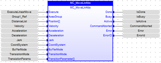
Structured Text
      (* Inst_MC_MoveLinAbsST example *)
Inst_MC_MoveLinAbs( ExecuteLinearMove, Group1_Ref, PositionList, Velocity, Acceleration, Deceleration, Jerk, CoordSystem, BufferMode, TransitionMode, TransitionParams );
IL
      BEGIN_IL"Instruction list"
This is a low-level language and resembles assembly
     CAL Inst_MC_MoveLinAbs( ExecuteLinearMove, Group1_Ref, PositionList, Velocity, Acceleration, Deceleration, Jerk, CoordSystem, BufferMode, TransitionMode, TransitionParams )
END_IL
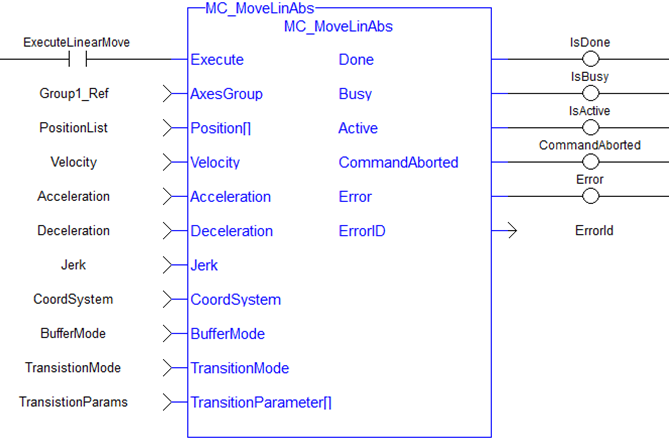
FBD
FFLD
 [Top]
[Top]


