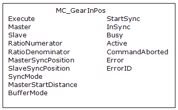
 MC_GearInPos
Description
SlaveCommandPosition = MasterActualPosition * RatioNumerator / RatioDenominator
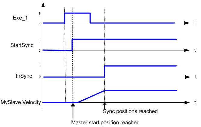
This function block also allows the application to specify sync positions for the master and slave axes. It is the point in which the master and slave axes become engaged in synchronous motion. When the master axis reaches the MasterStartDistance from the MasterSyncPosition, the slave axis begins to accelerate to the target velocity determined by the master axis velocity and the ratio. The slave axis arrives at the target velocity and the SlaveSyncPosition at the same time the master axis arrives at the MasterSyncPosition. At that time, the slave is locked on to the master and follows the master at the ratio specified. The slave axis continues to follow the master axis until this move is aborted.
Gearing functions can generate large accelerations while following the master. If the aborting function block has small, non-zero Jerk![]() In physics, jerk is the rate of change of acceleration; more precisely, the derivative of acceleration with respect to time, or small acceleration values, it can take a long time for an accelerating axis to reach the target velocity, or position of the aborting function block. If the Jerk and/or acceleration of the aborting function cannot be increased to suitable values, it may be desirable to:
In physics, jerk is the rate of change of acceleration; more precisely, the derivative of acceleration with respect to time, or small acceleration values, it can take a long time for an accelerating axis to reach the target velocity, or position of the aborting function block. If the Jerk and/or acceleration of the aborting function cannot be increased to suitable values, it may be desirable to:
- Abort the gearing function with an MC_GearOut with higher accelerations and/or Jerk values (or zero jerk
 In physics, jerk is the rate of change of acceleration; more precisely, the derivative of acceleration with respect to time value),
 - Execute the next MC motion function block such as MC_Halt.
Time to Reach the Target Velocity
While following the master, gearing functions can generate large accelerations. If the gearing function is aborted while the axis is currently accelerating, and the aborting function block has small non-zero Jerk or small acceleration values, it can take a long time to reach the target velocity, or position of the aborting function block. If the Jerk and/or acceleration of the aborting function cannot be increased to suitable values, it may be desirable to:
- Abort the gearing function with an MC_GearOut with higher accelerations and/or Jerk values (or zero jerk value),
- Execute the next MC motion function block such as MC_Halt.
Time Diagram
-
- This function block starts a motion-related action and therefore stores data for calculations and error checking. Please see Calling Function Blocks Multiple Times in the Same Cycle if you are using a dual-core controller.
Arguments
For more detail on how inputs and outputs work, refer to PLCopen Function Blocks - General Rules
Input
| Execute | Description | Requests to queue the slave gear ratio move |
| Data type | BOOL | |
| Range | 0, 1 | |
| Unit | n/a | |
| Default | — | |
| Master | Description |
Name of a declared instance of the AXIS_REF library function (for more details,About Axis Name and Number) |
| Data type | AXIS_REF | |
| Range | [1,256] | |
| Unit | n/a | |
| Default | — | |
| Slave | Description | AXIS_REF.AXIS_NUM is the slave axis number |
| Data type | AXIS_REF | |
| Range | [1,256] | |
| Unit | n/a | |
| Default | — | |
| RatioNumerator | Description | Numerator of master/slave ratio. The sign (+ or -) indicates the direction for the slave axis. |
| Data type | DINT | |
| Range | [-2147483648, 2147483647] | |
| Unit | n/a | |
| Default | — | |
| RatioDenominator | Description | Denominator of master/slave ratio. The sign (+ or -) indicates the direction for the master axis. The direction determines the sync trigger comparison direction for the slave.
|
| Data type | DINT | |
| Range | [-2147483648, 2147483647] | |
| Unit | n/a | |
| Default | — | |
| MasterSyncPosition | Description | Master axis sync position |
| Data type | LREAL | |
| Range | -1.7308 to 1.7308 (14 to 15 significant digits of accuracy) | |
| Unit | n/a | |
| Default | — | |
| SlaveSyncPosition | Description | Slave axis sync position |
| Data type | LREAL | |
| Range | -1.7308 to 1.7308 (14 to 15 significant digits of accuracy) | |
| Unit | n/a | |
| Default | — | |
| SyncMode | Description |
SyncMode determines the allowed conditions for synchronization: 0 = Normal synchronization. Prior to executing the MC_GearInPos function block, the Master axis position must be before the MasterSyncPosition by a distance greater than the MasterStartDistance. The Slave axis position must be before the SlaveSyncPosition. 1 = Immediate synchronization allowed. This mode is only allowed if both the master and slave axes have rollover = 0. If the conditions of SyncMode = 0 are not met, Synchronization is allowed even though the axis positions may be beyond their respective Sync Positions. The MasterStartDistance may be 0. If the MasterStartDistance is zero, the Slave axis will synchronize with the master the instant the master axis crosses the MasterSyncPosition. |
| Data type | INT | |
| Range | 0-1 | |
| Unit | n/a | |
| Default | — | |
| MasterStartDistance | Description | When the master axis reaches this distance before MasterSyncPosition, the slave axis begins its lock-on process.
|
| Data type | LREAL | |
| Range | 1.7-308 to 1.7308 (14 to 15 significant digits of accuracy) | |
| Unit | User unit | |
| Default | — | |
| BufferMode | Description | 1 = buffer |
| Data type | SINT | |
| Range | [1] | |
| Unit | n/a | |
| Default | — |
Output
| StartSync | Description | Indicates that the master axis has reached the MasterStartDistance from the MasterSyncPosition and the lock-on process has begun |
| Data type | BOOL | |
| InSync | Description | Indicated the slave axis is locked on to the master axis |
| Data type | BOOL | |
| Busy | Description | High from the moment the Execute input goes high until the time the move is ended |
| Data type | BOOL | |
| Active | Description | Indicates this move is the Active move |
| Data type | BOOL | |
| CommandAborted | Description | Indicates the move was aborted. If the abort arises because the inputs cause inconsistent motion, then this FB:
|
| Data type | BOOL | |
| Error | Description | Indicates an invalid input was specified or the move was terminated due to an error |
| Data type | BOOL | |
| ErrorID | Description | Indicates the error if Error output is set to TRUE |
| Data type | INT |
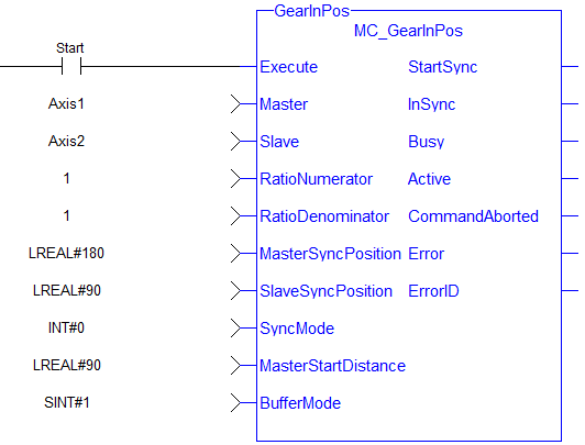
Example
Example Description
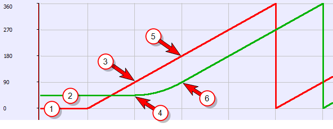
- Master and Slave are rotary axes with rollovers at 360 degrees.
- The Master initial position is 0 degrees and the slave initial position is 45 degrees.
- The GearInPos FB commands the slave to accelerate up to the geared ratio (1:1) during the master start distance (90 degrees) and be synchronized with the master at the master and slave sync positions.
|
|
Structured Text
(* MC_GearInPos ST example *)
Inst_MC_GearInPos( GearInPosReq, Axis1, Axis2, 2, 1, 0, 0, 0, 100.0, 1 );
//Inst_MC_GearInPos is instance of MC_GearInPos
GearInPosSync:= Inst_MC_GearInPos.InSync;
//store InSync output into user defined variable
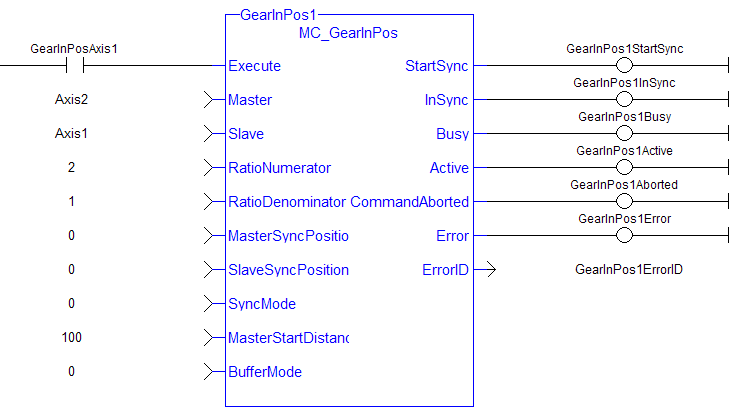
Ladder Diagram
 [Top]
[Top]


