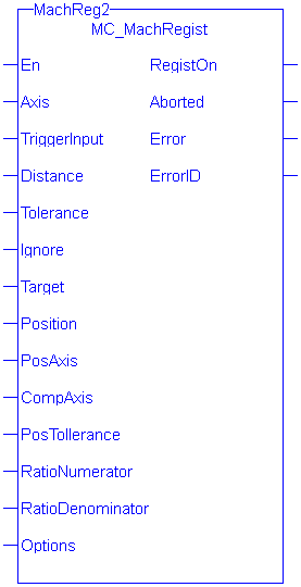
 MC_MachRegist
Description
This function block enables Mark-to-Machine registration and can be used on any servo or digitizing axis and with any move type. It is most frequently used in master/slave applications.
- A positive transition of the En input will start registration. The application may change the registration parameters while registration is active by changing the input values and causing another positive transition of the En input. The function block will then read and apply the new values.
- The axis number at the Axis input indicates the axis whose position, at the fast input, is used to determine if the mark is a good mark.
- The Distance, Tolerance, and Ignore inputs are used to determine whether or not the registration mark is good. For a mark to be recognized as good, it must be outside of the Ignore distance and the correct Distance from the previous mark +/- the Tolerance window. A mark is considered bad if it occurs outside of the “good tolerance band” and is not ignored. Both good marks and bad marks are recognized as marks, ignored marks are not recognized. If all marks are to be recognized as good marks, enter 0 at both Distance and Tolerance.
- The Distance value defines the distance between good marks. In Clear Lane and Product registration the Distance input value typically is the same as the Target input value. However in Print registration the Distance is typically not the same as Target.
- The Tolerance value is the distance, plus and minus, about Distance. Marks that are detected within this window are considered good marks and registration will occur. Marks that are detected outside this window and outside the Ignore band, are considered bad marks and registration will not occur. This window should be large enough to allow for the worst case error in the distance between the previous mark and the current mark.
- The Ignore value defines the distance from the previous mark where all marks detected by the fast input will be ignored. This is crucial when registering products that do not have Clear Lane registration marks.
- The Target input is the expected target position that is used to calculate how much registration compensation is to be applied when a registration mark is considered good. When a good mark is detected, the position of the PosAxis is compared to the Target position to calculate a correction. The registration correction will only be applied with master/slave move types.
- The Position input is the position value that the registration Axis position will be reset to when a good registration mark is detected.
- When a good mark occurs the position of the PosAxis is compared to the Target position and used to calculate the amount of registration compensation to apply to the CompAxis.
- Registration compensation is applied to the axis specified at the CompAxis input under the following conditions. If CompAxis is executing a slave move (i.e. MC_GearIn or MC_CamIn), the compensation is applied directly to the axis. If CompAxis is a master axis, the compensation is applied to the master offsets of all its slaves. This shifts the master’s position as seen by its slaves.
- The PosTolerance input is the distance, plus and minus, about the Target position used to determine if compensation will be applied. When a good mark occurs, the position of the PosAxis axis is checked to see if it lies within the window defined by PosTolerance. If it is in the window, compensation will be applied. If it is outside the window, compensation will not be applied even though a good mark was found.
- If PosAxis and CompAxis are different axes, the RatioNumerator and RatioDenominator inputs define the conversion factor for calculating the compensation value. This is needed because the amount of error between actual and target positions is determined by PosAxis’s position and the compensation is applied to the CompAxis. The RatioNumerator should typically be the number of User Units of CompAxis motion for one registration cycle and the RatioDenominator should typically be the number of User Units of PosAxis motion for one registration cycle. If PosAxis and CompAxis are the same, RatioNumerator and RatioDenominator should be the same value, thus resulting in a 1:1 ratio.
- The Option input defines various modes of operation for registration.
- The first bit, 0001H, selects Absolute or Resetting. This refers to the way in which the second mark and all subsequent marks are determined to be good marks. With both registration schemes, the very first mark detected is the starting point. With Resetting registration, when the next mark is detected, the position of that mark becomes the starting point for the next good mark detection calculation and so on. The starting point is “reset” with each good or bad mark. This feature allows the product to re-synchronize, if necessary, due to process issues like product shift, etc. In contrast, Absolute registration determines all good marks based on the very first mark. The position of the second and each subsequent mark is compared to an integer multiple of Distance from the very first mark. This method insures the product will always register to a known fixed distance.
- The third bit, 0004H, must always be 0. Mark-to-machine registration requires time-based capture.
-
- This function block starts a motion-related action and therefore stores data for calculations and error checking. Please see Calling Function Blocks Multiple Times in the Same Cycle if you are using a dual-core controller.
-
- Is this the right function block to use? See Deciding Which Function Blocks to Use for Registration and Registration Application Guide.
Arguments
Input
| En | Description | Rising edge of EN enables execution |
| Data type |
BOOL |
|
| Range |
0, 1 |
|
| Unit |
n/a |
|
| Default |
— |
|
| Axis | Description | Axis whose position is used to determine a good mark. |
| Data type | Axis_Ref | |
| Range | The range of .AXIS_NUM is [1,256] | |
| Unit | n/a | |
| Default | n/a | |
| TriggerInput | Description |
Structure specifying the fast input. The structure elements are: 0 = Touch Probe 1 / Capture Engine 0 1 = Touch Probe 2 / Capture Engine 1 Range is [0,1] Direction INT TrigID INT
|
| Data type | TRIGGER_REF | |
| Range | ||
| Unit | ||
| Default | ||
| Distance | Description | This is the expected distance between good marks. Along with Tolerance and Ignore, this value is used to determine if the mark detected by the fast input is a good mark. |
| Data type | LREAL | |
| Range | When converted to feedback units, the range is [-251,251-1]. This value must have the same sign as Ignore. | |
| Unit | user units | |
| Default | n/a | |
| Tolerance | Description | This value specifies the distance, plus or minus, about Distance to determine if the mark detected by the fast input is a good mark. |
| Data type | LREAL | |
| Range | When converted to feedback units, the range is [0 ,251-1] | |
| Unit | user units | |
| Default | n/a | |
| Ignore | Description | This value specifies the distance after the previous good mark in which any detected marks are ignored. |
| Data type | LREAL | |
| Range | When converted to feedback units, the range is [-251,251-1]. This value must have the same sign as Distance. | |
| Unit | user units | |
| Default | n/a | |
| Target | Description | This is the target position. This position is compared to the actual position captured by the fast input to determine the amount of registration compensation to apply. |
| Data type | LREAL | |
| Range | When converted to feedback units, the range is:
|
|
| Unit | user units | |
| Default | n/a | |
| Position | Description | The position the axis is set to when a good registration mark occurs. If the “Inhibit Reference on Good Mark” option is specified for the Option argument (see Options Table below), then this argument is not used and the position of the axis is not changed when a registration mark is encountered. |
| Data type | LREAL | |
| Range | When converted to feedback units, the range is:
|
|
| Unit | user units | |
| Default | n/a | |
| PosAxis | Description | The position of this axis at the time the fast input occurs is compared to the Target position to determine the amount of registration compensation to apply. |
| Data type | AXIS_REF | |
| Range | The range of .AXIS_NUM is [1,256] | |
| Unit | n/a | |
| Default | n/a | |
| CompAxis | Description | The calculated registration compensation is applied to this axis. |
| Data type | AXIS_REF | |
| Range | The range of .AXIS_NUM is [1,256] | |
| Unit | n/a | |
| Default | n/a | |
| PosTolerance | Description | This value specifies the distance, plus or minus, about the Target position to determine if the position will be accepted and compensation value is calculated and applied. |
| Data type | LREAL | |
| Range | When converted to feedback units, the range is [-251,251-1] | |
| Unit | user units | |
| Default | n/a | |
| RatioNumerator | Description | This value is typically the number of User Units of CompAxis motion for one product cycle. This value is used with RatioDenominator to create a conversion factor for calculating the compensation value when PosAxis and CompAxis are different axes. |
| Data type | DINT | |
| Range | When converted to feedback units, the range is [1,4294967295] | |
| Unit | user units | |
| Default | n/a | |
| RatioDenominator | Description | This value is typically the number of User Units of PosAxis motion for one product cycle. This value is used with RatioNumerator to create a conversion factor for calculating the compensation value when PosAxis and CompAxis are different axes. |
| Data type | DINT | |
| Range | When converted to feedback units, the range is [1,4294967295] | |
| Unit | user units | |
| Default | n/a | |
| Options | Description | Each bit enables/disables an option. The following table defines the bits. Any bits not defined are reserved. The third bit, 0004H, must be 0. |
| Data type | UINT | |
| Range | refer to the following options table | |
| Unit | n/a | |
| Default | n/a |
| Hexadecimal | Decimal | Option | Description |
|---|---|---|---|
| 0001 H | 1 | Absolute/Resetting | 0 = Resetting, 1 = Absolute |
| 0002 H | 2 | Reserved | 0 |
| 0004 H | 4 | Time/position based capture | 0 = time based capture, 1 = position based capture |
| 0008 H | 8 | Inhibit Reference on Good Mark | 0 = Perform reference, 1 = inhibit reference When this bit is set, the Position function block argument is unused and the axis position is not changed when a registration mark is encountered. |
| 0010H | 16 | Inhibit Master Compensation | 0 = Perform Master Compensation, 1 = Inhibit Master Compensation |
| 0020H | 32 | Inhibit Slave Compensation | 0 = Perform Slave Compensation, 1 = Inhibit Slave Compensation. |
Table 7-42: MC_MachRegist Options Table
Outputs
| RegistOn | Description |
Indicates registration is activated |
| Data type |
BOOL |
|
| Aborted | Description | Indicates registration has been terminated by MC_StopRegist. |
|
|
Data type | BOOL |
| Error | Description | Indicates an invalid input was specified or registration was terminated due to an error |
|
|
Data type | BOOL |
| ErrorID | Description | Indicates the error if Error output is TRUE. See table in PLCopen Function Block ErrorID Output. |
|
|
Data type | INT |
-
-
To use Capture Engine 1 modify the input PDOs that are used and add the Latch
 The control word is used to activate the drive's latch status machine. The latch control word is processed independently of the EtherCAT bus cycle. The status word is used to return the drive's latch status Position 1 parameter.
Related Functions
Examples
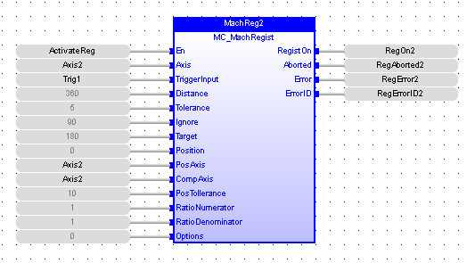
Function Block
Instruction List

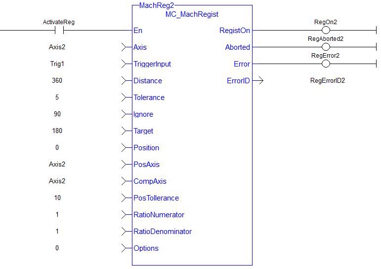
Ladder Diagram
Structured Text

 [Top]
[Top]


