 MLGearWriteRatSlp
Description
Set the Ratio Slope value of a selected Gear Pipe Block. Ratio Slope sets the limit at which step changes in ratio are implemented.
-
-
Be sure to set
RatioSlope < (Ratio * EtherCAT Update Rate). The Gear block will make a jump (without a ramp) from one gear to the next when the RatioSlope is greater than the Ratio change factor multiplied by the update rate scale factor.
-
-
Values lower then 1.0 can be entered, but require a leading zero (for example 0.8 instead of .8)
-
-
The GEAR block output will add a position offset to the GEAR block input when using a RatioSlope. See RatioSlope Offset in the Examples below.
Arguments
Input
|
BlockID |
Description |
ID number of an initialized Gear Pipe Block |
|
Data type |
DINT |
|
|
Range |
[-2147483648, 2147483648] |
|
|
Unit |
n/a |
|
|
Default |
— |
|
|
Slope |
Description |
New Ratio Slope value to be assigned to selected Gear Pipe Block. Values lower then 1.0 can be entered, but require a leading zero (for example 0.8 instead of .8) |
|
Data type |
LREAL |
|
|
Range |
— |
|
|
Unit |
1/sec |
|
|
Default |
— |
Output
|
Default (.Q) |
Description |
Returns TRUE if Ratio Slope value is changed in the selected Gear Pipe Block See more details here |
|
Data type |
BOOL |
|
|
Unit |
n/a |
Return Type
BOOL
Related Functions
Example
Structured Text
|
//Set the Ratio Slope value of Gear1 Pipe Block to 100 MLGearWriteRatSlp(PipeNetwork.GEAR1, 100.0);
|
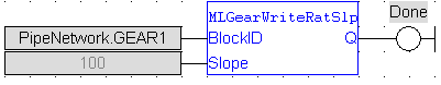
Ladder Diagram
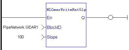
Function Block Diagram
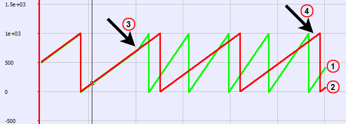
RatioSlope Offset
If MLGearWriteRatSlp is set as  to generate a ramp (instead of a step) when going from a gear ratio of 1 to 2, then there will be a position offset when the gear ratio settles as 2. In the image below the ratio goes from 1.0 to 2.0; Green is PN Gear Block Output and Red is Gearbox Input.
|
|
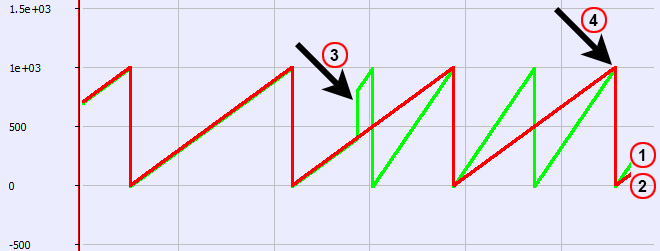
If MLGearWriteRatSlp is set without a ramp,  , then there will not be an offset.
|
|
 [Top]
[Top]


