 MCFB_StepAbsSwitchFastInput
Description
This function block performs a homing function by searching for an absolute positioned external physical switch. The switch must be connected to one of the two fast inputs![]() The inputs are taken into account at each cycle depending on the system periodicity (for example each millisecond). Under certain circumstances this can be insufficient when more accuracy is needed, or if a quick response is required from the system. To fill the gap, a drive may have some Fast Input connections (generally one or two). When an event happens that triggers a Fast Input (e.g. when a sensor sends a rising edge), the detection of a signal occurs faster (which can be 1000 times more accurate than the system periodicity). Then the timestamp associated with this input can be provided to the IPC to take corrective action on the Axis' AKD drive. (An Absolute Switch has two “Off” (or “On”) areas.
The inputs are taken into account at each cycle depending on the system periodicity (for example each millisecond). Under certain circumstances this can be insufficient when more accuracy is needed, or if a quick response is required from the system. To fill the gap, a drive may have some Fast Input connections (generally one or two). When an event happens that triggers a Fast Input (e.g. when a sensor sends a rising edge), the detection of a signal occurs faster (which can be 1000 times more accurate than the system periodicity). Then the timestamp associated with this input can be provided to the IPC to take corrective action on the Axis' AKD drive. (An Absolute Switch has two “Off” (or “On”) areas.
The following figure shows the function block I/O:
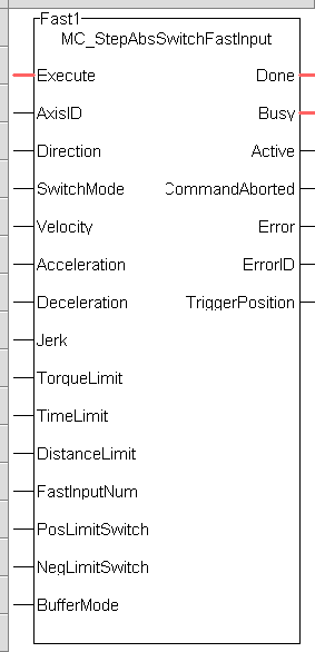
Figure 7-253: MCFB StepAbsSwitchFastInput
Input
|
Execute |
Description |
Request the homing step procedure at rising edge |
||||||||||||||
|
Data type |
BOOL |
|||||||||||||||
|
Range |
[0 , 1] |
|||||||||||||||
|
Unit |
N/A |
|||||||||||||||
|
Default |
— |
|||||||||||||||
|
AxisID |
Description |
Structure for specified Axis desired to home |
||||||||||||||
|
Data type |
||||||||||||||||
|
Range |
[1 , 256] |
|||||||||||||||
|
Unit |
N/A |
|||||||||||||||
|
Default |
— |
|||||||||||||||
|
Direction |
Description |
Define the axis homing direction
|
||||||||||||||
|
Data type |
BOOL |
|||||||||||||||
|
Range |
[0 , 1] |
|||||||||||||||
|
Unit |
N/A |
|||||||||||||||
|
Default |
— |
|||||||||||||||
|
SwitchMode |
Description |
Switch state to complete homing
|
||||||||||||||
|
Data type |
DINT |
|||||||||||||||
|
Range |
[0 , 3] |
|||||||||||||||
|
Unit |
N/A |
|||||||||||||||
|
Default |
— |
|||||||||||||||
|
Velocity |
Description |
Commanded velocity for the homing move |
||||||||||||||
|
Data type |
LREAL |
|||||||||||||||
|
Range |
— |
|||||||||||||||
|
Unit |
User unit/sec |
|||||||||||||||
|
Default |
— |
|||||||||||||||
|
Acceleration |
Description |
Commanded acceleration for the homing move |
||||||||||||||
|
Data type |
LREAL |
|||||||||||||||
|
Range |
— |
|||||||||||||||
|
Unit |
User unit/sec2 |
|||||||||||||||
|
Default |
— |
|||||||||||||||
|
Deceleration |
Description |
Commanded deceleration for the homing move |
||||||||||||||
|
Data type |
LREAL |
|||||||||||||||
|
Range |
— |
|||||||||||||||
|
Unit |
User unit/sec2 |
|||||||||||||||
|
Default |
— |
|||||||||||||||
|
Description |
Commanded jerk |
|||||||||||||||
|
Data type |
LREAL |
|||||||||||||||
|
Range |
— |
|||||||||||||||
|
Unit |
User unit/sec3 |
|||||||||||||||
|
Default |
— |
|||||||||||||||
|
TorqueLimit |
Description |
Maximum torque |
||||||||||||||
|
Data type |
LREAL |
|||||||||||||||
|
Range |
— |
|||||||||||||||
|
Unit |
User unit |
|||||||||||||||
|
Default |
— |
|||||||||||||||
|
TimeLimit |
Description |
Maximum time for homing move to complete. If exceeded the homing procedure will error out. 0= no time limit |
||||||||||||||
|
Data type |
TIME |
|||||||||||||||
|
Range |
— |
|||||||||||||||
|
Unit |
sec |
|||||||||||||||
|
Default |
— |
|||||||||||||||
|
DistanceLimit |
Description |
Maximum distance for homing move to complete. If exceeded the homing procedure will error out. 0= no distance limit |
||||||||||||||
|
Data type |
LREAL |
|||||||||||||||
|
Range |
— |
|||||||||||||||
|
Unit |
User unit |
|||||||||||||||
|
Default |
— |
|||||||||||||||
|
FastInputNum |
Description |
|||||||||||||||
|
Data type |
BOOL |
|||||||||||||||
|
Range |
[0 , 1] |
|||||||||||||||
|
Unit |
N/A |
|||||||||||||||
|
Default |
— |
|||||||||||||||
|
PosLimitSwitch |
Description |
The positive direction limit switch input I/O point |
||||||||||||||
|
Data type |
BOOL |
|||||||||||||||
|
Range |
[0 , 1] |
|||||||||||||||
|
Unit |
N/A |
|||||||||||||||
|
Default |
— |
|||||||||||||||
|
NegLimitSwitch |
Description |
The negative direction limit switch input I/O point |
||||||||||||||
|
Data type |
BOOL |
|||||||||||||||
|
Range |
[0 , 1] |
|||||||||||||||
|
Unit |
N/A |
|||||||||||||||
|
Default |
— |
|||||||||||||||
|
BufferMode |
Description |
Define the homing move start action
|
||||||||||||||
|
Data type |
SINT |
|||||||||||||||
|
Range |
[0 , 5] |
|||||||||||||||
|
Unit |
N/A |
|||||||||||||||
|
Default |
— |
Output
|
Done |
Description |
Indicates the move completed successfully. The Command Position has reached the endpoint |
||||||||||||||
|
Data type |
BOOL |
|||||||||||||||
|
Unit |
N/A |
|||||||||||||||
|
Busy |
Description |
High from the moment the Execute input is one-shot to the time the move is ended |
||||||||||||||
|
Data type |
BOOL |
|||||||||||||||
|
Unit |
N/A |
|||||||||||||||
|
Active |
Description |
Set when the function block is active |
||||||||||||||
|
Data type |
BOOL |
|||||||||||||||
|
Unit |
N/A |
|||||||||||||||
|
CommandAborted |
Description |
Indicates the move was aborted |
||||||||||||||
|
Data type |
BOOL |
|||||||||||||||
|
Unit |
N/A |
|||||||||||||||
|
Error |
Description |
Signals that an error has occurred within the function block |
||||||||||||||
|
Data type |
BOOL |
|||||||||||||||
|
Unit |
N/A |
|||||||||||||||
|
ErrorID |
Description |
Indicates the error if Error output is set to TRUE
|
||||||||||||||
|
Data type |
INT |
|||||||||||||||
|
Unit |
N/A |
|||||||||||||||
|
TriggerPosition |
Data type |
LREAL |
||||||||||||||
|
Range |
- |
|||||||||||||||
|
Unit |
User units |
|||||||||||||||
|
Default |
- |
Usage
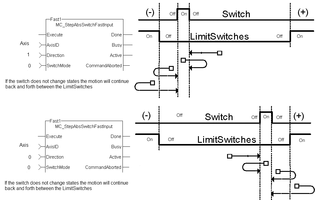
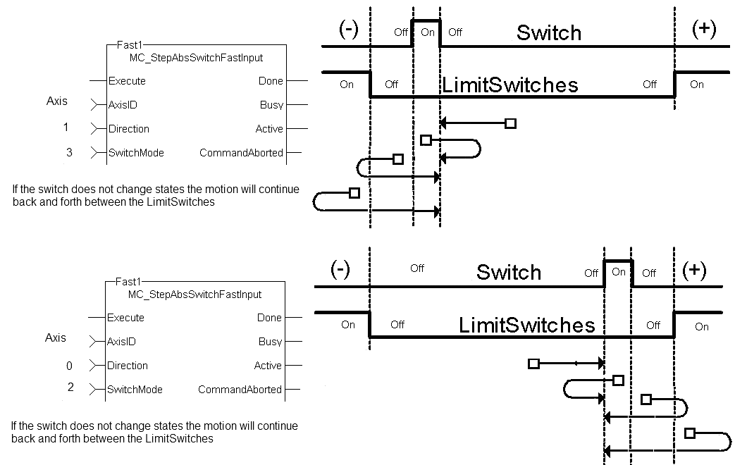
- The homing is commanded in the most likely direction were the sensor can be found. In this example (-).
- If any LimitSwitch is found during Homing
 The Homing procedure allows, based on a position measurement, to set a position offset to the motor in order to ensure it is physically at the home position (any of them), then a special process is started in the opposite direction, the AbsSwitch is searched to switch off (or On, depending on SwitchMode setting). The Edge (passed by), and homing process is restarted in the original direction and with the same conditions. This ensures that the end conditions are always same.
.
Related Functions
Example
Structured Text
|
Execute_1 :=1; (*Positive_Switch and Negitive_Switch are physical hardware in Dictionary. *)
Inst_MC_StepAbsSwitchFastInput( Execute_1, Axis1, 0, 0, 10000.0,Acceleration:=10000.0, 10000.0, 0, 0, 0, 0, 0, Positive_Switch , Negitive_Switch , 0)
HomeComplete := Inst_MC_StepAbsSwitchFastInput.Done; HomeBusy := Inst_MC_StepAbsSwitchFastInput.Busy; HomeActive := Inst_MC_StepAbsSwitchFastInput.Active; HomeAborted := Inst_MC_StepAbsSwitchFastInput.CommandAborted; HomeError := Inst_MC_StepAbsSwitchFastInput.Error; HomeErrorID := Inst_MC_StepAbsSwitchFastInput.ErrorID; HomeTriggerPosition := Inst_MC_StepAbsSwitchFastInput.TriggerPosition; |
FBD

Ladder Diagram
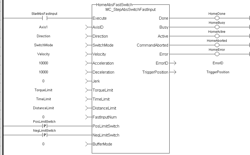
(* PosLimitSwitch, NegLimitSwitch are declared I/O points *)
 [Top]
[Top]


