MLTrigInit
Description
Initializes a Trigger object for use in a PLC![]() "Programmable Logic Controller"
A Programmable Logic Controller, PLC, or Programmable Controller is a digital computer used for automation of industrial processes, such as control of machinery on factory assembly lines.
Used to synchronize the flow of inputs from (physical) sensors and events with the flow of outputs to actuators and events Program. Function
"Programmable Logic Controller"
A Programmable Logic Controller, PLC, or Programmable Controller is a digital computer used for automation of industrial processes, such as control of machinery on factory assembly lines.
Used to synchronize the flow of inputs from (physical) sensors and events with the flow of outputs to actuators and events Program. Function![]() A function calculates a result according to the current value of its inputs. A function has no internal data and is not linked to declared instances. block is automatically called if a Trigger Block is added to the Pipe Network, with user-defined settings entered in the Pipe Blocks Properties screen.
A function calculates a result according to the current value of its inputs. A function has no internal data and is not linked to declared instances. block is automatically called if a Trigger Block is added to the Pipe Network, with user-defined settings entered in the Pipe Blocks Properties screen.
The Trigger object monitors a selected Fast Input![]() The inputs are taken into account at each cycle depending on the system periodicity (for example each millisecond). Under certain circumstances this can be insufficient when more accuracy is needed, or if a quick response is required from the system. To fill the gap, a drive may have some Fast Input connections (generally one or two). When an event happens that triggers a Fast Input (e.g. when a sensor sends a rising edge), the detection of a signal occurs faster (which can be 1000 times more accurate than the system periodicity). Then the timestamp associated with this input can be provided to the IPC to take corrective action and captures the time of a rising or falling edge event. With the time and pipe position information the Trigger object extrapolates the axis position when the Fast Input event occurred.
The inputs are taken into account at each cycle depending on the system periodicity (for example each millisecond). Under certain circumstances this can be insufficient when more accuracy is needed, or if a quick response is required from the system. To fill the gap, a drive may have some Fast Input connections (generally one or two). When an event happens that triggers a Fast Input (e.g. when a sensor sends a rising edge), the detection of a signal occurs faster (which can be 1000 times more accurate than the system periodicity). Then the timestamp associated with this input can be provided to the IPC to take corrective action and captures the time of a rising or falling edge event. With the time and pipe position information the Trigger object extrapolates the axis position when the Fast Input event occurred.
Parameters to enter include the name of the Pipe Block, the Axis where the Fast Input is located, the number of the desired Fast Input, and whether to trigger on the rising or falling edge of the input.
-
-
Trigger objects are normally created in the Pipe Network using the graphical engine. Then you do not have to add MLTrigInit function blocks to their programs. Parameters are entered directly in pop-up windows, and the code is then automatically added to the current project.
Arguments
Input
|
BlockID |
Description |
ID number of a created Pipe Block |
|
|
Data type |
DINT |
|
|
Range |
[-2147483648, 2147483648] |
|
|
Unit |
N/A |
|
|
Default |
— |
|
Input_Axis |
Description |
Name of the axis where the Fast Input is located |
|
|
Data type |
STRING |
|
|
Range |
— |
|
|
Unit |
N/A |
|
|
Default |
— |
|
InputID |
Description |
ID number of the Fast Input 0 = Touch Probe 1 / Capture Engine 0 1 = Touch Probe 2 / Capture Engine 1 Range is [0,1] |
|
|
Data type |
DINT |
|
|
Range |
[-2147483648, 2147483648] |
|
|
Unit |
N/A |
|
|
Default |
— |
|
EdgeID |
Description |
Trigger at rising or falling edge of Fast Input. Enter 1 for rising edge |
|
|
Data type |
DINT |
|
|
Range |
[0 , 2] |
|
|
Unit |
N/A |
|
|
Default |
1 (Rising edge) |
Output
|
Default (.Q) |
Description |
Returns TRUE if function block is executed See more details here. |
|
|
Data type |
BOOL |
|
|
Unit |
N/A |
Return Type
BOOL
Related Functions
See Also
- Fast Inputs with Pipe Network Motion
- Fast Inputs with PLCOpen
- Fast Homing Example with the Pipe Network Motion Engine Axis Pipe Block
- Fast Homing Example with the PLCopen Motion Engine
- Pipe Network Registration and Fast Homing
- Registration Position Capture Example with Pipe Network Trigger Block
Example
Structured Text
//Create and Initiate a Trigger Pipe Block named “Trigger” and set it up to receive the trigger signal from Axis1, capture engine 0, and the rising edge of the signal
TRIGGER := MLBlkCreate( 'TRIGGER', 'TRIGGER' );
MLTrigInit( TRIGGER, 'Axis1', 0, 1 );
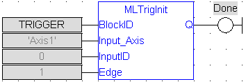
Ladder Diagram
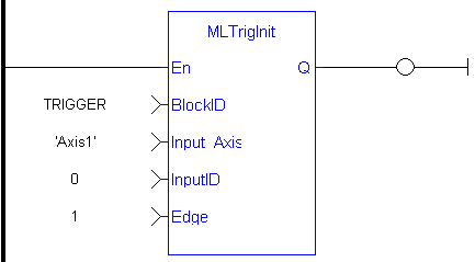
Function Block Diagram