AKT2G-BRC-000-000
Brake Chopper Terminal
Jump to a section on this page:
The AKT2G-BRC-000 EtherCAT![]() ***EtherCAT is an open, high-performance Ethernet-based fieldbus system. The development goal of EtherCAT was to apply Ethernet to automation applications which require short data update times (also called cycle times) with low communication jitter (for synchronization purposes) and low hardware costs Terminal contains high-performance capacitors for stabilizing supply voltages.
***EtherCAT is an open, high-performance Ethernet-based fieldbus system. The development goal of EtherCAT was to apply Ethernet to automation applications which require short data update times (also called cycle times) with low communication jitter (for synchronization purposes) and low hardware costs Terminal contains high-performance capacitors for stabilizing supply voltages.
The AKT2G-BRC-000 can be used, for example, in conjunction with the AKT2G-SM-L50-000 or AKT2G-SM-L15-000 stepper motor terminal. Low internal resistance and high pulsed current capability enable good buffering in parallel with a power supply unit.
Return currents are stored, particularly in the context of drive applications, thereby preventing overvoltages. If the recovery energy exceeds the capacity of the capacitors, energy can be dissipated via an external ballast resistor. The switching threshold for this can be parameterized via the KAS IDE![]() "Integrated development environment"
An integrated development environment is a type of computer software that assists computer programmers in developing software.
IDEs normally consist of a source code editor, a compiler and/or interpreter, build-automation tools, and a debugger.
"Integrated development environment"
An integrated development environment is a type of computer software that assists computer programmers in developing software.
IDEs normally consist of a source code editor, a compiler and/or interpreter, build-automation tools, and a debugger.
Technical Data
| Technical Data | AKT2G-BRC-000-000 |
|---|---|
| Technology | Brake chopper |
| Rated voltage | up to 72 V |
| Capacitance | 155 µF |
| Ripple current | 10 A in continuous operation |
| Internal resistance | < 10 mΩ |
| Overvoltage protection | Standard 50 V, parameterizable via CoE data |
| Recommended ballast resistor | ZB8110* |
| Overvoltage control range | Standard 1 V, parameterizable via CoE data |
| Ballast resistor clock rate | load-dependent, max. 100 µs, 2-point control |
| Electrical isolation | 1500 V |
| Diagnostics | Temperature on the PCB |
| Message to E-bus | Data for the switch-on behavior of the resistor as well as current and supply voltage |
| PE contact | no |
| Screen connection | - |
| E-Bus current consumption | typ. 80 mA |
| Power consumption from power contacts | 0 mA |
| Bit width in process image | 88 bit |
| Electrical connection to mounting rail | - |
| Addition to EtherCAT Terminals with power contact | yes, left side without PE |
| Addition to EtherCAT Terminals without power contact | yes |
| Dimensions (W x H x D) | approx. 15 mm x 100 mm x 70 mm (width aligned: 12 mm) |
| Configuration | Via CoE data |
| Weight | approx. 90 g |
| permissible ambient temperature range during operation | 0 °C ... +55 °C |
| permissible ambient temperature range during storage | -25 °C ... +85 °C |
| permissible relative humidity | 95 %, no condensation |
| Mounting | on 35 mm mounting rail conforms to EN 60715 |
| Vibration/shock resistance | according to EN 60068-2-6/EN 60068-2-27, see also Installation instructions for enhanced mechanical load capacity |
| EMC immunity/emission | conforms to EN 61000-6-2 / EN 61000-6-4 |
| Protection class | IP20 |
| Installation position | Any, see Mounting and Wiring of I/O Terminals |
| Approval | CE, cULus |
* depending on the application, a larger resistor may be necessary
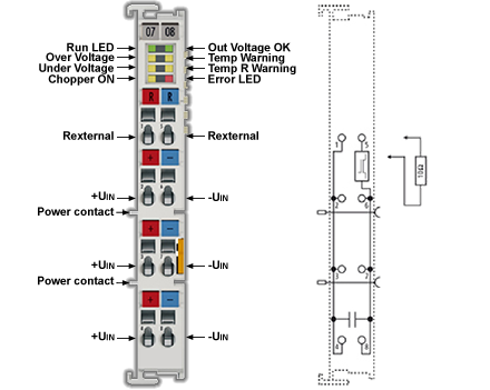
LEDs and Pin Assignment
-
-
Correct supply voltage is necessary for operation!
In addition to the supply voltage via the contacts on the front panel, the voltage from the E-bus must also be present in order for the terminal to work properly, since the integrated logic of the Bus Terminal is supplied with this voltage. The Bus Terminal does not work if the supply is incorrect.
-
-
Match the resistor power to the expected power!
When selecting the external resistor, make sure that the rated power of the resistor is matched to the expected power, since otherwise the resistor and adjacent components can be damaged. In addition, the temperature model is to be adapted to this resistor.
Pin Assignment
| Terminal Point | Description | |
|---|---|---|
| Name | No. | |
| R 50 V (Rexternal) | 1 | + connection of external resistor |
| 50 V (+Uin) | 2 | + supply voltage connection |
| 50 V (+Uin) | 3 | + supply voltage connection |
| 50 V (+Uin) | 4 | + supply voltage connection |
| R GND (Rexternal) | 5 | - connection of external resistor |
| GND (-Uin) | 6 | - supply voltage connection |
| GND (-Uin) | 7 | - supply voltage connection |
| GND (-Uin) | 8 | - supply voltage connection |
LEDs
| LED | Color | Meaning | |
|---|---|---|---|
| RUN | green | This LED indicates the terminal's operating state: | |
| off | State of the EtherCAT State Machine : INIT = initialization of the terminal | ||
| flashing | State of the EtherCAT State Machine: PREOP = function for mailbox communication and different standard-settings set | ||
| single flash | State of the EtherCAT
State Machine: SAFEOP =
verification of the Sync Manager channels and the distributed clocks. The outputs remain in safe state. |
||
| on | State of the EtherCAT State Machine: OP = normal operating state; mailbox and process data communication is possible | ||
| flickering | State of the EtherCAT State Machine: BOOTSTRAP = function for firmware updates of the terminal | ||
| Out voltage OK | green | ON | Supply voltages are OK, there are no errors |
| OFF |
|
||
| Over voltage | yellow | ON | The supply voltage has exceeded the threshold value for overvoltage. |
| Temp warning | yellow | ON | Temperature threshold value for the temperature on the PCB has been exceeded. |
| Under voltage | yellow | ON | The supply voltage is too low, or has fallen below the corresponding threshold value in the CoE data. |
| Temp R warning | yellow | ON | The “I2T warning level” threshold value has been exceeded. |
| Chopper On | yellow | ON | The external resistor is switched on. |
| Error | red | ON + “Undervolt age” LED | The supply voltage is not connected or is so low that the “supply voltage” and “ResistorCurrent” values cannot be read. |
| ON + “Temp R Warning” LED + “Overvolta ge” LED | There is an overtemperature in the internal temperature simulation for the external resistor. | ||
Brake Chopper Quick Start
Proceed as follows for standard commissioning of the AKT2G-BRC-000 with an external resistor.
- Install the AKT2G-BRC-000 in the E-bus terminal segment on an EtherCAT coupler,.
- For operation the AKT2G-BRC-000 requires a supply voltage at connections 2 and 6 (UIN) of the terminal as well as a power supply via the E-Bus. The following must be observed:
- The supply voltage must be at least 18 VDC.
- The resistor must be designed to handle the expected power and must be parameterized accordingly via CoE Init-Commands.
- The voltage supply must be designed for the switching on of the corresponding resistor.
- Supply quality: the most stable and noise-free supply possible must be ensured.
- Parameterize the resistor you are using with CoE Init-Commands according to the data sheet for the resistor.
- Reverse any previous parameter changes by means of a CoE reset: enter 0x64616F6C in object 0x1011:01.
- Enter the ambient temperature of the resistor in °C in 0x8000:15.
- Enter the thermal resistance of the electrical resistor to the environment in m°C/W in 0x8000:16.


