![]()
 Function
![]() A function calculates a result according to the current value of its inputs. A function has no internal data and is not linked to declared instances. - Configures the Fast Input
A function calculates a result according to the current value of its inputs. A function has no internal data and is not linked to declared instances. - Configures the Fast Input![]() The inputs are taken into account at each cycle depending on the system periodicity (for example each millisecond). Under certain circumstances this can be insufficient when more accuracy is needed, or if a quick response is required from the system. To fill the gap, a drive may have some Fast Input connections (generally one or two). When an event happens that triggers a Fast Input (e.g. when a sensor sends a rising edge), the detection of a signal occurs faster (which can be 1000 times more accurate than the system periodicity). Then the timestamp associated with this input can be provided to the IPC to take corrective action for the axis by writing the expected settings in the Latch
The inputs are taken into account at each cycle depending on the system periodicity (for example each millisecond). Under certain circumstances this can be insufficient when more accuracy is needed, or if a quick response is required from the system. To fill the gap, a drive may have some Fast Input connections (generally one or two). When an event happens that triggers a Fast Input (e.g. when a sensor sends a rising edge), the detection of a signal occurs faster (which can be 1000 times more accurate than the system periodicity). Then the timestamp associated with this input can be provided to the IPC to take corrective action for the axis by writing the expected settings in the Latch![]() The control word is used to activate the drive's latch status machine. The latch control word is processed independently of the EtherCAT bus cycle. The status word is used to return the drive's latch status Control Word.
The control word is used to activate the drive's latch status machine. The latch control word is processed independently of the EtherCAT bus cycle. The status word is used to return the drive's latch status Control Word.
Fast input can be armed on falling or rising edge![]() A rising edge is the transition of a digital signal from low to high. It is also called positive edge.
A rising edge is the transition of a digital signal from low to high. It is also called positive edge.
Arguments
Input
|
En |
Description |
Enables execution |
|
Data type |
BOOL | |
|
Unit |
N/A | |
|
Default |
- | |
|
AxisID |
Description |
ID name of the Axis Block |
|
Data type |
DINT |
|
|
Range |
— |
|
|
Unit |
N/A |
|
|
Default |
— |
|
|
InputID |
Description |
ID of the FastInput of an axis, (i.e., IN1 and IN2 on S300
|
|
Data type |
DINT |
|
|
Range |
[0, 1] |
|
|
Unit |
N/A |
|
|
Default |
— |
|
|
Mode |
Description |
|
|
Data type |
DINT |
|
|
Range |
[0, 2] |
|
|
Unit |
N/A |
|
|
Default |
— |
Output
Related Functions
See Also
- Fast Inputs with Pipe Network Motion
- Fast Homing Example with the Pipe Network Motion Engine Axis Pipe Block
- Fast Homing Example with the PLCopen Motion Engine
- Pipe Network Registration and Fast Homing
- Registration Position Capture Example with Pipe Network Trigger Block
Example
Structured Text
|
MLAxisCfgFastIn( PipeNetwork.Axis1, 0, 1 ) ;
|
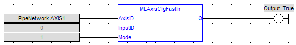
Ladder Diagram
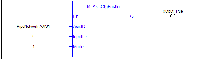
Function Block Diagram