EnDat 2.2
|
|
This chapter is only valid for SMM R_03-00-004. |

General Information
- To support EnDat 2.2, the servo drive must be fitted with X23 connector (connector option F3 – refer to (➜ # 1, Part Number Scheme) and (➜ # 1, Connector pinout)
- AKD2G with Functional Safety Option 3 with F3 Option (X23 connector) supports all safe EnDat 2.2 encoders, linear and rotary, SIL2 and SIL3, except for encoder models with more than 12 multiturn bits
Initial Safety Setup
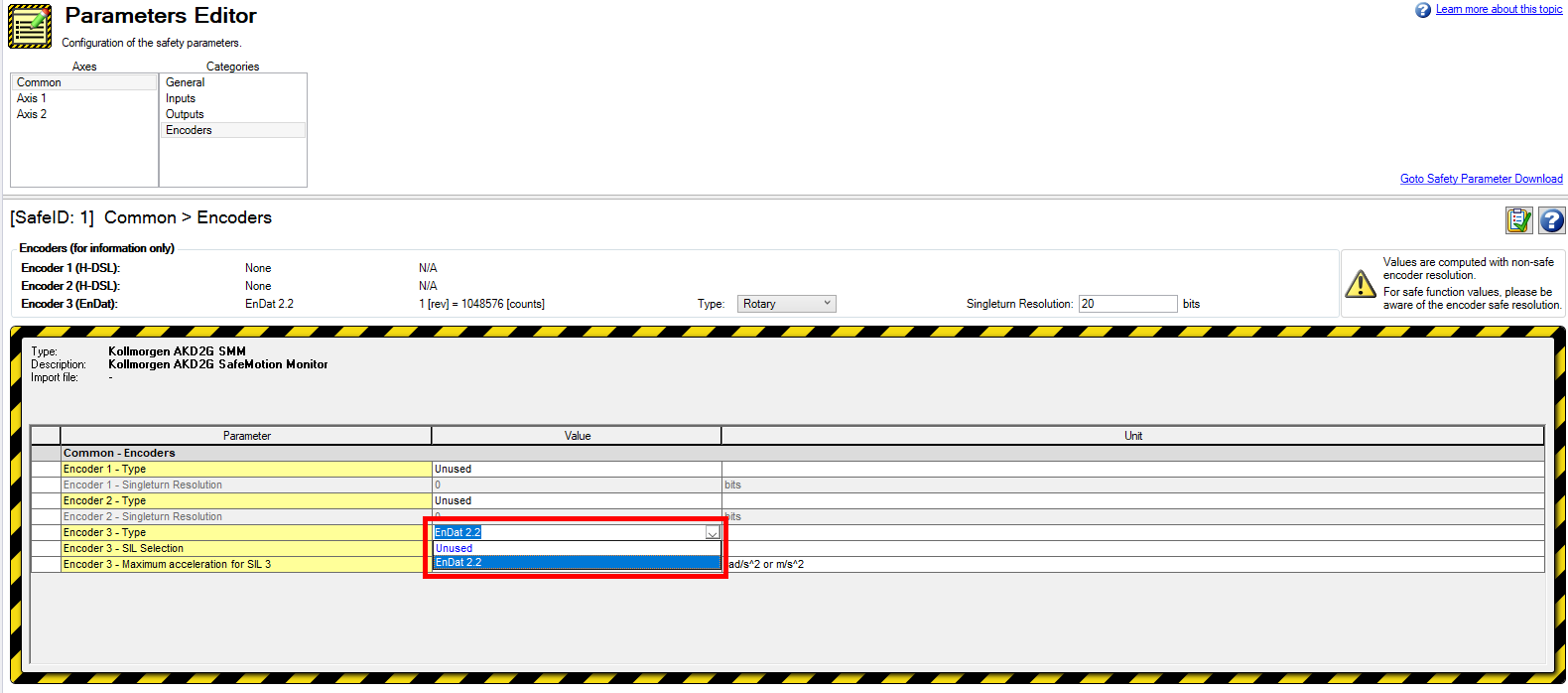
All AKD2G support only one safe EnDat 2.2 encoder per servo drive at a time through the X23 connector. You don't need to specify a particular EnDat 2.2 encoder model.
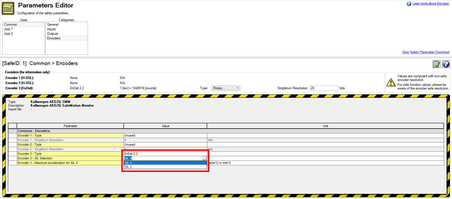
Choose between SIL2 and SIL3.
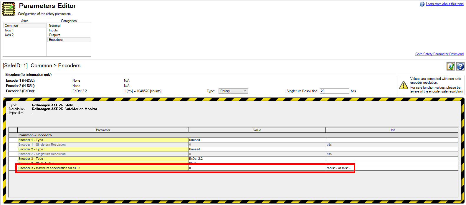
To achieve SIL3 with an EnDat 2.2 encoder, specify a maximum acceleration for its step monitoring. For a rotary encoder the specified value is shown in rad/s2 and for a linear one the value is shown in m/s2.
The resulting diagnostic coverage must be ≥99%. The diagnostic coverage is calculated as follows:
Expectation_Interval = (3/2) * alpha_max * (385 [µs])2
Diagnostic_Coverage = 100% * (Possible_Safe_Positions - 2*Expectation_Interval) / Possible_Safe_Positions
Encoders
-
-
Limitation:
When using EnDat 2.2 in SIL3 applications (SIL3 is selected in the safe parameters), there is a limitation which makes the SMM go into safe state when the motor is moving in the negative direction and it crosses the encoder's rollover point at a certain speed.
Remarks:
The minimum speed, in rpm, at which this situation happens can be computed with the following formula for rotary encoders:
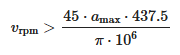
where amax is the maximum acceleration for a given encoder in rad/s².
For linear encoders, depending on the encoder scale, the bug is not reproducible (for example if the scale does not contain a zero position). For encoder scales that can trigger this bug, the minimum speed in m/s can be computed as:
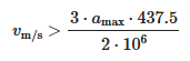
where amax is the maximum acceleration for a given encoder in m/s².
For example, this results in a speed of approximately 627 rpm for an EQI1131 rotary encoder, whose maximum acceleration parameter is 105 rad/s². For a LC415 linear encoder, whose maximum acceleration parameter is 100 m/s² , it would result in a speed of approximately 6.6 cm/s.
Please note that this speed value is an approximation, and real-world values will be slightly affected by noise and timing.
Workaround:
If SIL3 is required and the application also requires moving in the negative direction at a speed above the threshold previously defined, a possible workaround is to mount the encoder/motor in such a way that no rollover occurs during normal machine operation.
Rotary Encoders
Due to the parameter range of the permissible acceleration parameter, the diagnostic coverage for SIL3 is always met for rotary encoders. Refer to the encoder datasheet of the manufacturer to get the permissible acceleration.
Linear Encoders
For linear encoders the diagnostic coverage depends on the Measuring Length (ML) specified in the encoder datasheet. This is used as the `Possible_Safe_Positions` in the calculation.
Example for a linear encoder with a permissible acceleration of "alpha_max = 100 [m/s2]" and a Measuring Length (ML) of "Possible_Safe_Positions = 2,040 [mm]":
Expectation_Interval = (3/2) * 100 [m/s2] * (385 * 10-6 [s])2 = 22,234 [µm]
DC = 100% * (2,040 * 10-3 [m] - 2 * Expectation_Interval) / (2,040 * 10-3 [m]) = 99.99%
Refer to the encoder datasheet of the manufacturer for the permissible acceleration.