Express Setup View
This view lets you quickly and easily configure your drive and motor. To accomplish this:
-
There is a limited set of Views in the View Tree, including the Express Setup View.
There a groups of parameters in the Express Setup View which you walk through to configure the servo drive.
-
A progress bar lets you know how far you are through the process.
-
There are visual indicators that let you know if configuration is required or it is complete. Defining a value for a parameter marks the item as configured. You may also click on the icon to "Mark as resolved" or "Unresolve" a parameter so it may be resolved at a later time.

Group Needs Attention Further configuration is required by elements or parameters in the group. 
Group Is Configured The group is fully configured. 
Parameter Needs Configuration The parameter requires configuration.
Make a selection, enter a value, or click on the icon and select "Mark As Resolved" to accept the current value.
Once a selection has been made or a value entered this icon will change to indicate the parameter is configured.
You can not complete express setup with unconfigured parameters.

Parameter Configuration is Recommended Further configuration is recommended. When shown, the parameter may benefit from further configuration but is not required. 
Parameter may be skipped 
Parameter is Configured This parameter is fully configured.
You may change a parameter from being configured or resolved to an unresolved state by clicking the Resolved button.
-
The content of some groups are reactive to other groups, such as Brake, I/Os, and Regen Resistor. Editing content in one could have effect on another. The status of a Group can change from being Configured to Needs Attention if parameters are affected.
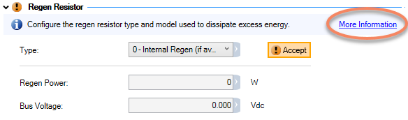
If you are stuck, click the More Information link at the top right corner of most groups.
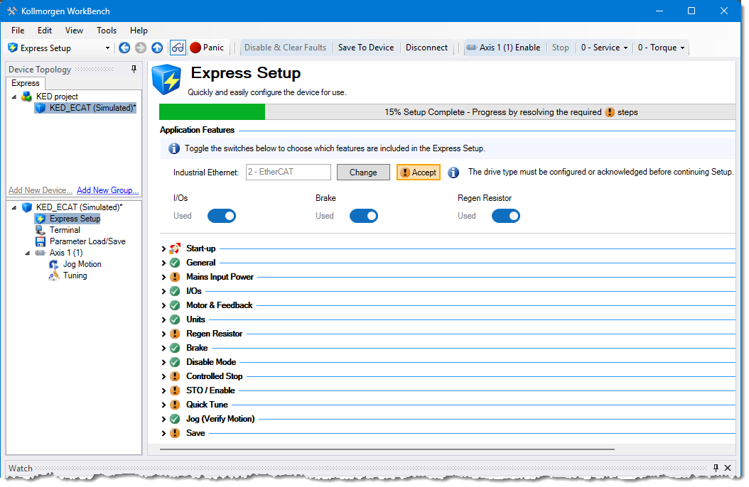
Application Features
The Application Features section lets you define some basic information about the devices. Enabling a feature adds that functionality to the Express Setup Express Setup View. 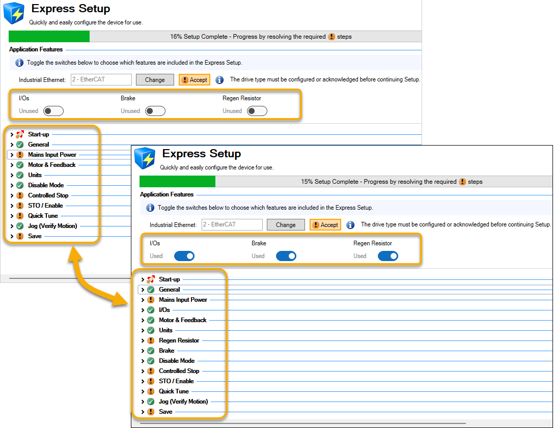
| Feature | Description |
|---|---|
| Industrial Ethernet | This entry is set to EtherCAT by default. Clicking the Change button allows you to change the defined Industrial Ethernet protocol but this will not take effect until the device has been power-cycled. |
| I/Os | Using this feature adds the I/Os group to the Setup view. |
| Brake | Using this feature adds the Brake group to the Setup view. |
| Regen Resistor | Using this feature adds the Regen Resistor group to the Setup view. |
Startup
The items in Start-up allow you to confirm you're connected to the device (Blink), remove old data (Reset to Default), and upload existing parameters that have been saved from a previous configuration (Load from File…).
General Group
This section allows you to set and change the drive's name.
Mains Input Power Group
This section allows you to configure some power settings for the servo drive. A power meter is shown with the ranges defined.
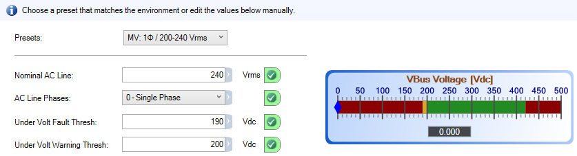
- Presets
- Several presets are available. Select one if it matches your environment otherwise fill in the parameters.
- Nominal AC Line
- Sets the operating voltage of the drive.
- AC Line Phases
- Sets whether the AC line input to the DC bus is single or three phase.
- Under Volt Fault Thresh
- Sets the value at which an under voltage fault will occur.
- Under Volt Warning Thresh
- Sets the value at which an under voltage warning will occur.
I/Os Group
This group allows you to configure the digital inputs and outputs to drive actions, controlled stops and limits. The setup first reads information from the drive and displays any default settings, such as DIN3 being set to Hardware Enable or configured Actions (see About Actions for more information).
To configure an I/O setting:
-
Click on the Edit Configuration button on the right side of the group.
-
Select the Function you want to have assigned to the I/O. Depending upon the Function selected there will be additional categories to define, such as an axis or all axes.
-
Click OK.
Some functions, such as Controlled Stop, affect information in other Groups. This is shown next to the function description including a link to the affected Group. In some cases the configuration from is too complex for Express Setup and the the Full Setup will be needed.
|
Function |
Description |
Options |
|---|---|---|
|
Positive Limit Switch |
Set a control to limit motion for an axis when a hardware limit is reached. |
Axis: Select which axis the limit switch applies to. Polarity: Set the polarity to high or low for triggering this function. |
|
Negative Limit Switch |
||
|
HW Enable |
Upon a Hardware Enable any faults may be cleared or retained. By default this is DIN3 for Axis 1
|
Axis: Select which axis (or all axes) Hardware Enable. Mode: Select whether faults are cleared or not upon Hardware Enable. Polarity: Set the polarity to high or low for triggering this function. |
|
Controlled Stop |
This function allows you to set a controlled stop which brings an axis or axes to a standstill in a controlled manner. The behavior is defined in the Controlled Stop Group group.
|
Axis: Select which axis (or all axes) the stop applies to. Mode: Select the state of the axis upon stopping. The axis can:
Polarity: Set the polarity to high or low for triggering this function. |
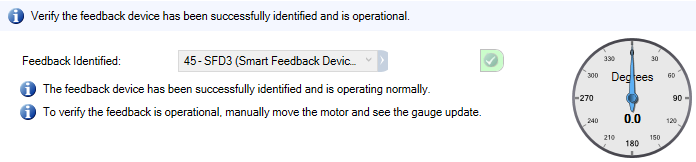
Motor & Feedback Group
This group provides information about the motor and feedback states. When a motor is connected to the servo drive this content is automatically populated. A gauge (linear or rotary) shows the device's position.
Units Group
The Units group helps you to set the proper units for the axis mechanics. If you are using the using the default setting (Motor Only) then this group does not need to be edited or confirmed. 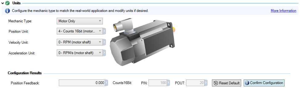
There are three primary measures of motion: position, velocity, and acceleration. You must first choose units of measurement for each of these, and then enter the details of the mechanics in order to scale the chosen units appropriately.
- Mechanic Type
- Select the general type of mechanic this axis will be used on . Your selection will change the graphic and associated parameters. For any mechanic type other then Motor Only you have the option of selecting a gearbox type and parameters.
- Position Unit
- This sets the position units to counts, radians, degrees, or Custom. The position is reported under Configuration Results.
- Velocity Unit
- This sets the units for velocity.
- Acceleration unit
- This sets the units for acceleration.
- Custom Position Unit
- Select the units for reporting the Position Feedback under Configuration Results if the Position Units is set to Custom.
Regen Resistor Group
Define the regen resistor type that is used to dissipate excess energy. The default setting is for an Internal Regen. When selecting an External Regen there will be several pre-defined models you may choose from, otherwise you will need to define the parameters.
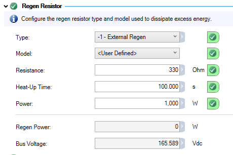
- Type
- Select the Internal Regen option if it is included with your motor or you can specify an External Regen resistor.
- Model
- Select the external regen resistor model, or choose User Defined if your model is not in the list. This option is only available when Type is set to External Regen.
- Resistance
- Set the desired external, user-defined resistance value. Valid values are 0 to 330 Ω. This option is only available with User Defined model type. This parameter must be confirmed individually.
- Heat-up Time
- Define the time-to-fault (in seconds) when input power steps from 0 to 150% of the Power value.
The servo drive's regen resistor protection algorithm continuously calculates the power dissipated in the resistor and processes that power value through a single pole low pass filter to model the regen resistor's thermal inertia.
This option is only available with User Defined model type. This parameter must be confirmed individually. - Power
- This is the regen resistor's power fault level. If the power exceeds this value (in Watts), a fault will be thrown.
This option is only available with User Defined model type. This parameter must be confirmed individually. - Regen Power
- Displays the current wattage.
- Bus Voltage
- Displays the measured DC bus voltage.
Brake Group
The contents of the Brake group allow you to set whether a motor brake exists or not. If a brake is present you may set whether the hardware checks the brake or ignores brakeapplications and faults are ignored.
Additionally there are buttons to control brake behavior.
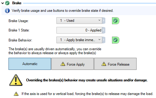
- Brake Usage
- This determines whether a brake is used or not.
Value
Status
0
Motor brake does not exist.
1
Motor brake exists and brake hardware circuitry checks are enabled.
100 For special, low current, brake applications, brake faults are bypassed with this setting. - Brake State
- This displays the current state of the brake
- Brake Behavior
- Sets whether the brake applies immediately or when the motor has stopped.
- Automatic
- The default behavior in which the brakes are automatically applied and released.
Changing the automatic behavior of the brake to Force Apply or Force Release can create dangerous situations. Use caution!
- Force Apply
- Select this button to apply force to the brake.
- Force Release
- Select this button to release the brake.
Disable Mode Group
Select how the axis responds to a "disable" command from the Terminal or Industrial Ethernet protocol. This selection can affect whether setting Controlled Stop is required or optional.
| Value | Description | Behavior |
|---|---|---|
|
0 |
Disable axis immediately |
Disable axis immediately. If AXIS#.MOTOR.BRAKEIMM = 1, the brake is applied as soon as the power stage disables. |
|
1 |
Dynamic brake immediately |
Use the dynamic brake to ramp down. The axis remains in the dynamic brake state after the motor has stopped. The axis is disabled in the sense that it does not close the control loop and cannot perform motion, but PWM stays active. |
|
2 |
Controlled stop then disable |
Use a controlled stop to ramp down and then disable the axis. |
|
3 |
Controlled stop then dynamic brake |
Use a controlled stop to ramp down, and then use dynamic brake. The axis remains in the dynamic brake state after the motor has stopped. The axis is disabled in the sense that it does not close the control loop and cannot perform motion, but PWM stays active. |
-
-
Use caution with vertical loads when modifying this parameter. Coordinate this parameter's correct setting properly with the axis brake settings. If these settings are not coordinated, then vertical loads may have no stopping or holding force when the axis is disabled and the load could fall.
Controlled Stop Group
Controlled Stop is required if a brake is present.
- Disable Timeout
- This is a timer which starts when the axis is disabled. After this timeout elapses the actual state of the drive is compared to the Disable Mode setting. If the states do not match a fault is reported and the hardware immediately executes the Disable Mode setting. Setting this to 0 disables the timeout.
- Deceleration
- This is the deceleration value for the controlled stop process in RPM/s.
- Velocity Threshold
- This is the velocity threshold for the motor to be considered at zero velocity.
- Velocity Threshold Timeout
- This is the time value for the motor velocity to be within the Velocity Threshold before the drive considers the motor to be at zero velocity.
STO/ Enable Group
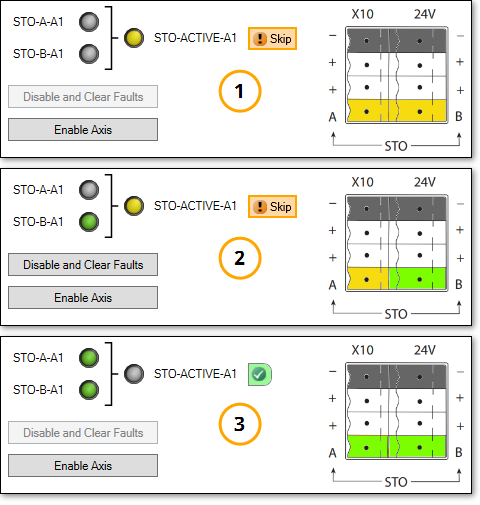
This group lets you verify that the Safe Torque Off (STO) is wired correctly. While the STO-ACTIVE signal is yellow the STO lines are not wired correctly. When the STO lines are wired correctly the LEDs (signals) are green, and the STO-ACTIVE signals are gray. A colorized pinout are helps with visualizing the wiring.
In the image below we see an example of setting up STO using a Kollmorgen Essentials Drive.
-
Example 1 shows incomplete wiring. The signals coming in (STO-A and STO-B) are gray and STO-ACTIVE is yellow.
-
Example 2 shows partially complete wiring. STO-A is gray (not properly wired) and STO-B is green (properly wired). STO-ACTIVE is yellow. The STO function will not work.
-
Example 3 shows properly wired inputs (green LEDs) and STO_ACTIVE is gray indicating that it is available, but not active.
-
-
AKD2G drives with Functional Safety 2 or Functional Safety 3 must be configured using the Full Setup. This is due to FS2 and FS3 being controlled by the SMM (SafeMotion Monitor).
Quick Tune Group
Quick Tune performs a quick inertia measurement with a connected motor. Based on the measurements a target bandwidth is set and tuning gains achieve this bandwidth.
After Quick Tune is complete, if the application requires stiffer or looser behavior, the slider tuner may be used to fine tune behavior. If the mechanics are more complicated and audible noise or ringing is present, the Performance Servo Tuner or Manual Tuning may be required to resolve these more advanced systems.
To run Quick Tune simply click through the buttons in order:
-
Switch to Serice Torque Mode
-
Enable Axis
-
Start Quick Tune
The results can be fine-tuned using the Override Bandwidth setting or the slider.
-
-
Overriding the Achieved Bandwidth can cause the system to be unstable, such as having a run-away motor. Use this option with care.
The Disable Axis button is available at all times should you need to stop the axis.
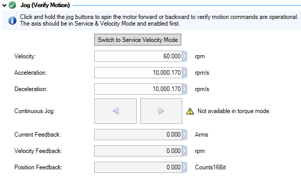
Jog (Verify Motion) Group
This group lets you verify motion commands are operational.
|
|
|
Rotary Motors |
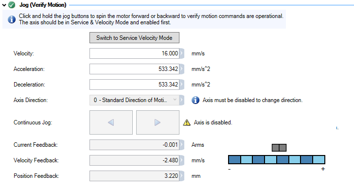
Linear Motors |
- Switch to Service Velocity Mode
- Click this button to switch out or torque mode and enable the Continuous Jog buttons.
- Velocity
- This field sets the jog velocity in RPM. The default is 60 RPM.
- Acceleration
- This field sets the acceleration ramp for jog moves in RPM/s.
- Deceleration
- This field sets the deceleration ramp for jog moves in RPM/s.
- Axis Direction
- Set the direction of motion, either Standard or Reversed. The axis must be disabled to switch the direction.
- Continuous Jog
- When the axis is in Service Velocity mode these buttons are active. Press and hold the button to move the motor in a positive or negative direction.
- Current Feedback
- This field displays the measured actual q-component current reading in Arms.
- Velocity Feedback
- This field displays the velocity feedback in RPM as it is received in the velocity loop.
- Position Feedback
- This field displays the position feedback value. The value represents the feedback after the following operations have been performed:
- Homing offset
- User offset
- Axis direction
- Position loop feedback gain
- Modulo if enabled
- Position Gauge
- This is a graphical representation of the axis position.
Save Group
The Save group lets you save this configuration to the servo drive or to a file for use on other drives. An information box is displayed if there are parameters which still need to be resolved. The information includes whether the parameter is required or optional, and provides links to the group.

- Save to Device
- Clicking this button saves the servo drive configuration.
- Save to File
- Clicking this button promts you to save a Parameter File (*.akd) so the configuration may be used on other servo drives of the same model.