Set Unit Scaling and Modulo
Prior to downloading, the Virtual Axis and AKD2G EtherNet/IP and WorkBench Unit Scaling and Modulo must be set.
Axis 1 Rotary Virtual Axis and AKD2G EtherNet/IP and WorkBench Unit Scaling
-
- On the AKD2G-SPI axis, Modulo is only necessary when using a Rotary axis.
Set WorkBench Units
In the Studio 5000 Sample project, Axis 1 is configured as a Virtual Axis in the MotionGroup under the name Axis1_Rotary.
The Units are in millidegrees with a:
- Conversion Constant of 1.0 (where 360000 = 360 degrees).
- Position Unwind of 360000.
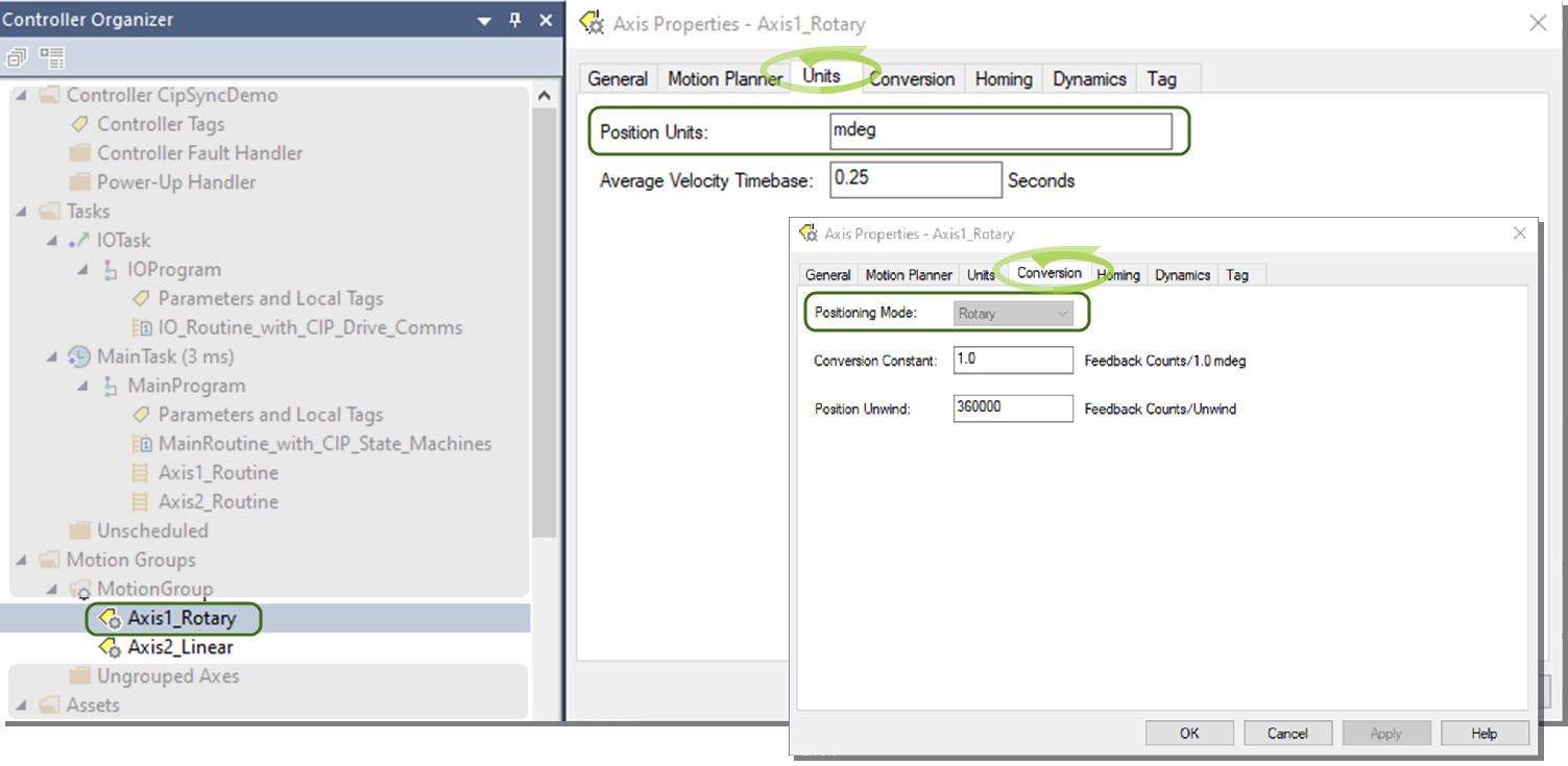
This is correlated in the Axis 1 Units and EtherNet/IP Scaling in WorkBench.
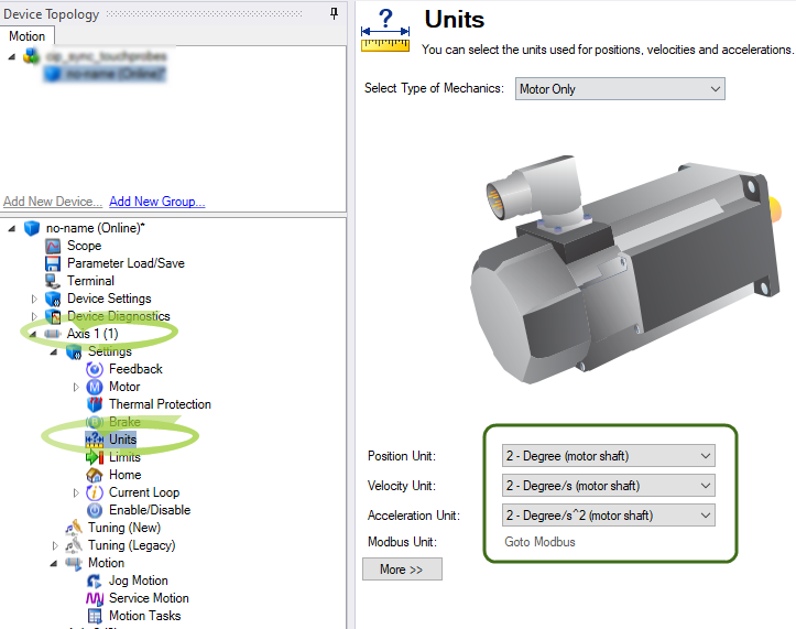
The Sample project and drive setup assumes Axis 1 is a direct drive rotary where the application units are in degrees.
Setting EtherNet/IP Units Scaling
For WorkBench units to align with EtherNet/IP units (and the Virtual Axis), it is necessary to scale the ratio input and ratio output for position, velocity, and acceleration units.
In WorkBench, navigate to Device Settings > Communications > EtherNet/IP > Axis 1 > Scaling tab.
The scaling is:
- Ratio Input: 360000 (EIP counts).
- Ratio Output: 1 (motor rev).
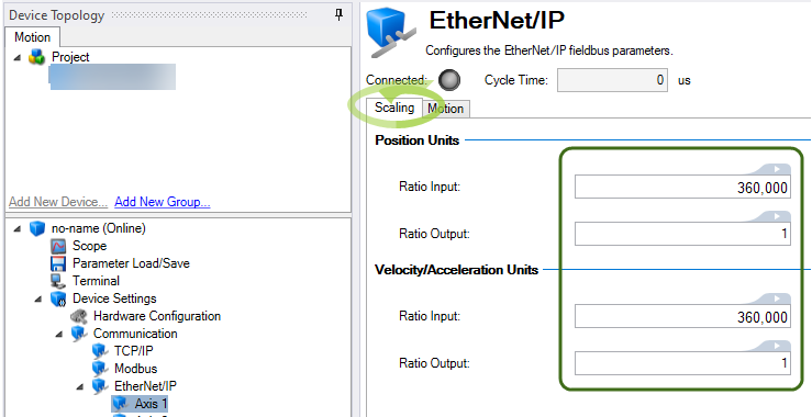
This facilitates scaling for the Real Axis in the drive to follow the Virtual Axis’ trajectory when a Motion Instruction (i.e., MAJ) is used.
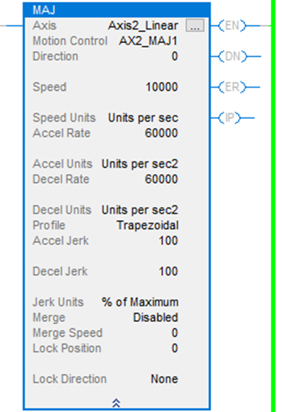
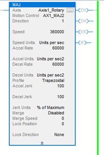
Example:
- Speed is set to 360000 or 360 deg/s.
- Accel/Decel are set to 60000 or 60 deg/s^2.
Setting Modulo
-
- On the AKD2G-SPI axis, Modulo is only necessary when using a Rotary axis.
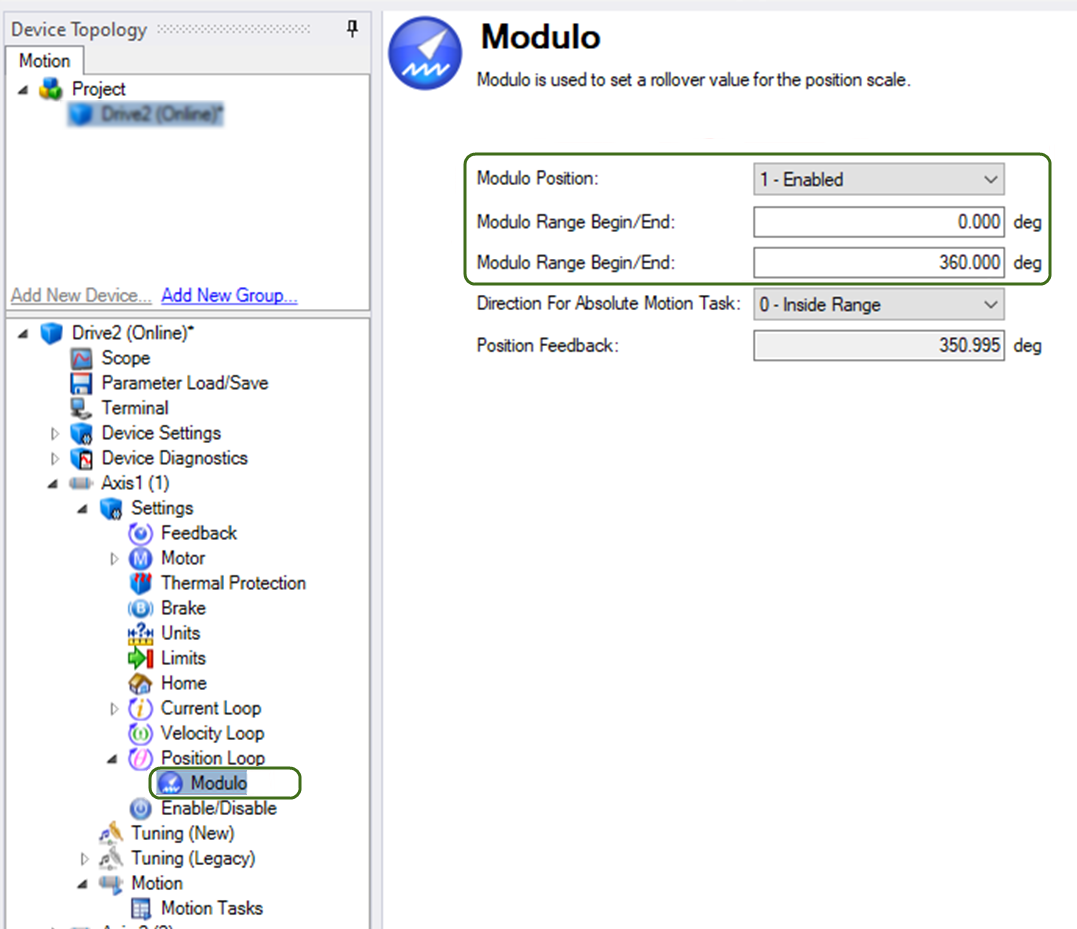
Since Axis 1 is setup as Rotary and the Virtual Axis has a Position Unwind of 360000 (mdeg), it is very important to:
- Enable the Modulo.
- Set the range in the AKD2G-SPI for Axis 1 so the axis never exceeds the range of the Position Unwind of the Virtual Axis.
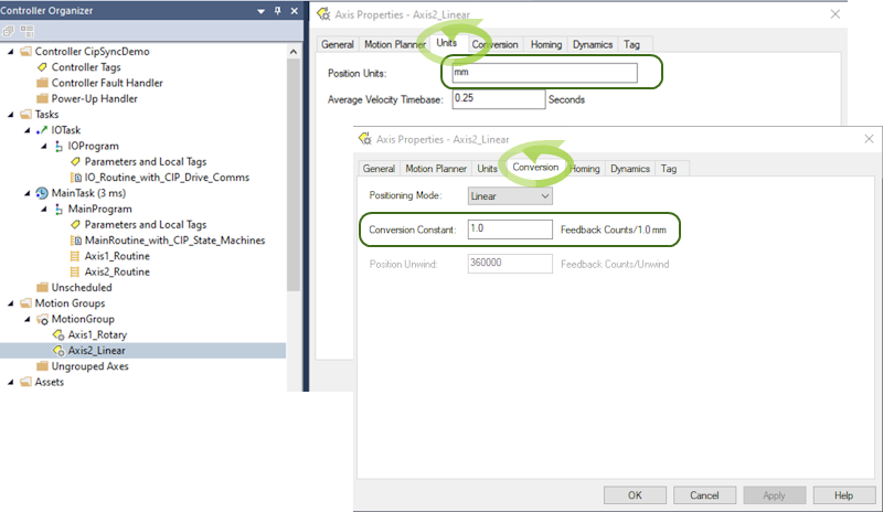
Axis 2 Linear Virtual Axis and AKD2G EtherNet/IP and WorkBench Unit Scaling
In the sample project, a second virtual axis was created in the Motion Group in Studio 5000 named Axis2_Linear to demonstrate the case of a linear axis in the application.
- Units are assumed to be millimeters and a Conversion Constant of 1.0.
- Feedback Counts/1.0 mm.
- Since the Virtual Axis is declared with a Linear Positioning Mode, the Position Unwind is grayed out.
- This makes it unnecessary to enable Modulo in Axis 2 of the AKD2G-SPI.
- In the Sample project, a second Virtual Axis (i.e., Axis2_Linear) was created in the MotionGroup to demonstrate the case of a linear axis in the application.
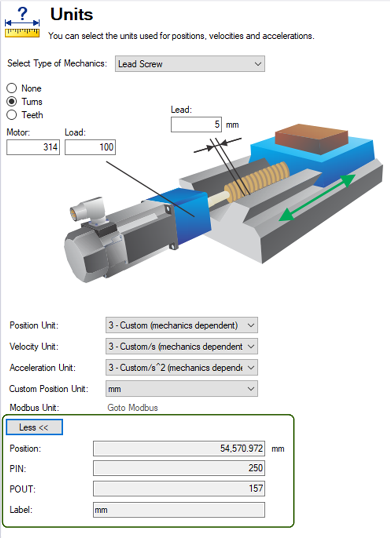
The ballscrew actuator used in creating and testing the Sample project uses these mechanics:
-
5 mm ballscrew with a 3.14 to 1 gear reducer.
-
WorkBench units were set normally to model the mechanics.
-
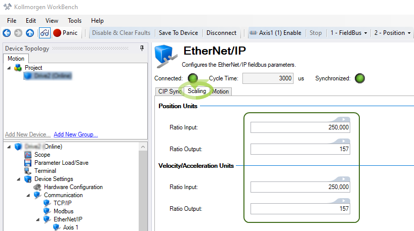
Click the More button to view the calculated PIN and POUT for WorkBench units (i.e., PIN = 250 and POUT = 157).
Note the Ratio Input and Ratio Output under the Scaling view (Communication > EtherNet/IP > Axis
- Ratio Input: 250 x 1000 (to handle the integer to floating point scaling).
- Ratio Output: 157.
This facilitates scaling for the Real Axis in the drive to follow the Virtual Axis’ trajectory when a Motion Instruction (i.e., MAJ) is used.
Example:
- Speed is set to 10000 (equivalent to 10 mm/s).
- Accel/Decel are set to 60000 (equivalent to 60 mm/s^2).