Verifying CIP Sync Mode and Synchronized/Locked State
In these steps, you will conduct a series of preliminary checks after going online.
Troubleshooting information for a common time synchronization error is provided.
- Verify the CIP Sync mode and the Synchronized and Locked States.
- Complete the second set of checks.
Procedure
- Navigate to the AKD2G Module (the drive) (Controller Organizer > Ethernet).
- Right-click and select Properties.
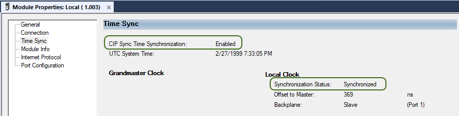
- Select Time Sync in the list and verify these settings:
- CIP Sync Time Synchronization: Enabled
- Synchronization Status: Synchronized
- Switch to WorkBench Online with the AKD2G-SPI drive.
- Select the drive_name (Online).
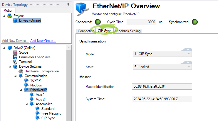
- Open the CIP Sync tab in the EtherNet/IP Overview.
(drive_name (Online) > Device Settings > Communication > EtherNet/IP > CIP Sync) - Connected: Indicator lamp is illuminated and green.
- Cycle Time: Displays the RPI set in the PLC and connection of the Module Properties of the AKD2G drive.
- Synchronized: Indicator lamp is illuminated and green.
- Mode: 1 - CIP Sync (reports the EIP.PLLMODE)
- State: 6 - Locked (reports the EIP.PLLSTATE)
- Data is reported in the Master Identification and System Time fields.
- These are read-only values from the PLC and vary.
- The key is to check that these fields are populated with data.
The EtherNet/IP Overview has these settings:
At the top of the EtherNet/IP Overview:
In the CIP Sync tab under Synchronization:
In the CIP Sync tab under Master:
Enable Time Synchronization Warning
If the settings displayed in the EtherNet/IP Overview are not correct, one possible root cause is forgetting to check the Enable Time Synchronization check box in the PLC’s Controller Properties > Date/Time tab.
Studio 5000 reports this Warning in the Errors window:

The text reads:
Warning: Controller has a motion group defined but does not have time synchronization enabled. For the axes in the motion group to function, there has to be one controller or valid module in the local backplane configured to be the CST master.
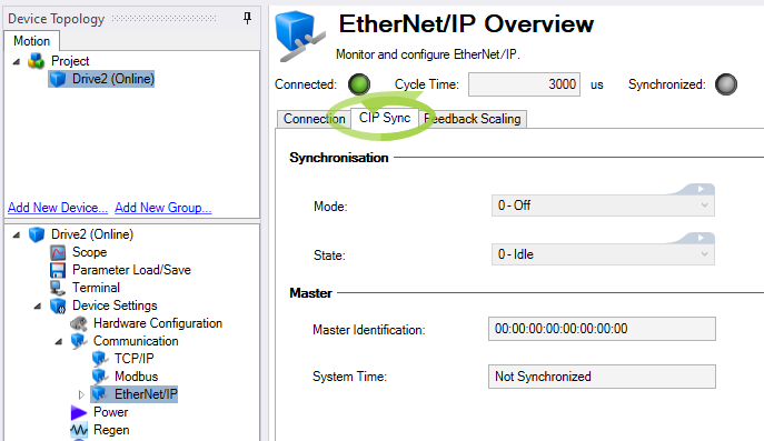
When this error is returned, the settings in the EtherNet/IP Overview and the CIP Sync tab show:
WorkBench Settings
At the top of the EtherNet/IP Overview:
- Connected: Indicator lamp is illuminated and green.
- Cycle Time: Displays the RPI set in the PLC and connection of the Module Properties of the AKD2G drive.
- Synchronized: Indicator lamp is OFF.
In the CIP Sync tab under Synchronization:
- Mode: 0 - Off (reports the EIP.PLLMODE)
- State: 0 - Idle (reports the EIP.PLLSTATE)
In the CIP Sync tab under Master:
- Master Identification: Data is all zeroes.
- System Time: Not Synchronized.
Solution
- In Studio 5000, go Offline.
- Select the Enable Time Synchronization check box.
See Part 15: Enable Time Synchronization. - Save and download the program to the PLC.
- Open WorkBench and go Online.
- Open the CIP Sync tab under EtherNet/IP Overview and review the settings shown in Step 4 at the start of this section.