


Biquad Custom Filters
| Parameter | Description | Drive Keyword |
|---|---|---|
|
PL.KP |
Position Loop Proportional Gain |
|
|
VL.ARTYPE# |
Anti-Resonace Filter Type |
|
|
VL.ARZF# |
Filter Zero Cutoff Frequency |
|
|
VL.ARZQ# |
Filter Zero Q Value |
|
|
VL.ARPF# |
Filter Pole Frequency |
|
|
VL.ARPQ# |
Filter Pole Q Value |
|
|
VL.KI |
Velocity Loop Integral Gain |
|
|
VL.KP |
Velocity Loop Proportional Gain |
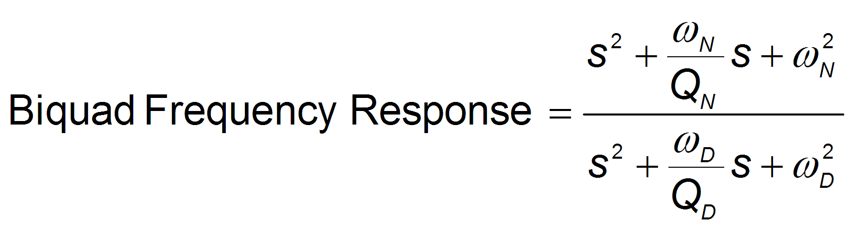
A biquad is a flexible filter which can be thought of ascomprising of two simpler filters: a zero (numerator) and a pole (denominator). In fact, the pre-defined Low Pass, Lead Lag, and Resonator (Notch) filters are really just special cases of the biquad filter.
Both the zero (numerator) and the pole (denominator) have a flat frequency response at low frequencies and a rising frequency response at high frequencies. The transition frequency and damping must be specified for both the numerator and denominator.
Analyzing the numerator and denominator, the frequency response calculation is simple: if the numerator and denominator are plotted in dB, the biquad response is numerator – denominator. Understanding how the numerator and denominator work is crucial in understanding how a biquad frequency response is created.
How the Biquad Works
Review: The Controller [C] trace shows the frequency response of VL.KP, VL.KI, PL.KP, AR Filters 1 & 2
Note: Here VL.KP is set to 1.0 so that the gain of the system is at 0dB
The Biquad is an extremely flexible filter and requires four values:
-
Numerator Frequency
-
Numerator Q
-
Denominator Frequency
-
Denominator Q
Note: All previous filter types are a Biquad, the GUI calculates the four parameters in a more user friendly way.
Common Custom Uses:
-
Solve complex controls problems
-
Get multiple filter effects in a single filter
How to Specify the Biquad Filter Using Terminal Commands
To specify a biquad filter, you must specify the frequency and Q for both the zero and the pole on anti-resonance filter 3. To do this, see the following example using the terminal commands that sets:
- Filter Type = Biquad
- Zero frequency = 100 Hz
- Zero Q = 0.7
- Pole frequency = 1000 Hz
- Pole Q = 0.8
AXIS#.VL.ARTYPE3 0
AXIS#.VL.ARZF3 100
AXIS#.VL.ARZQ3 0.7
AXIS#.VL.ARPF3 1000
AXIS#.VL.ARPQ3 0.8
Biquad Filter Examples
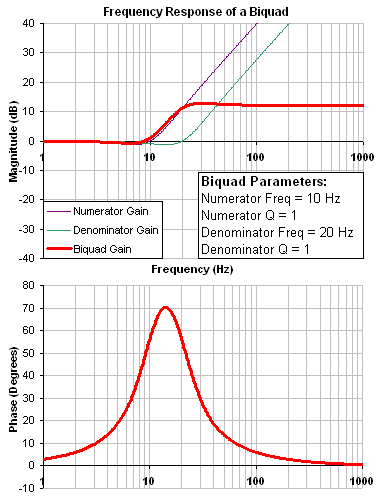
Following is an example of a biquad filter similar to a Lead Lag filter type. To help understand how to determine the frequency response of the biquad, the numerator and denominator response have been plotted. If the denominator is subtracted from the numerator the biquad response is the result.
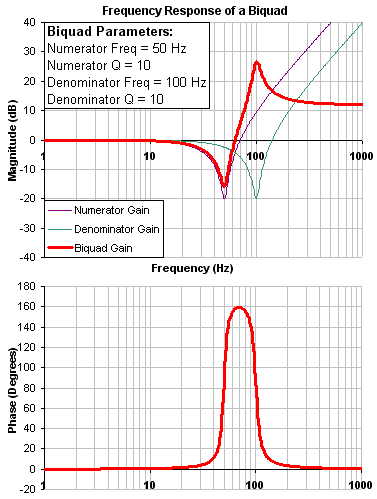
The biquad filter is very flexible which allows custom filters to be designed. Below is an example of a resonance filter using a biquad. Notice how the high Q values affect the numerator and denominator. This gives a biquad frequency response similar to a mechanical resonance.
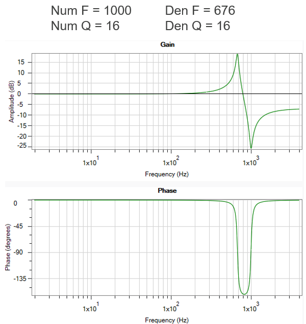
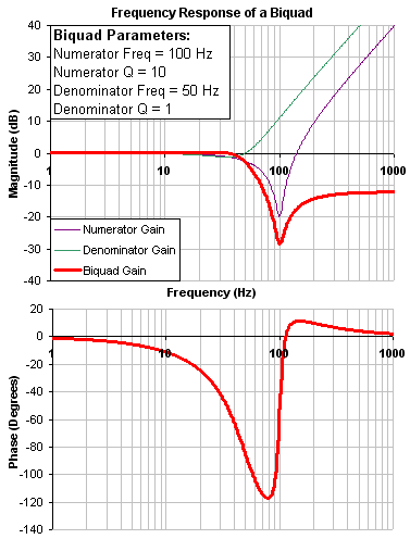
The previous examples used a numerator frequency lower than the denominator frequency, yielding a positive gain in high frequencies. If the denominator frequency is lower than the numerator frequency, then high frequencies will have a negative gain. This is an example where the numerator frequency is higher than the denominator. Notice the high frequencies have a negative gain.
Biquad Calculations
In the s-domain, the linear biquad response is calculated:
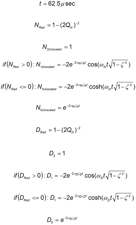
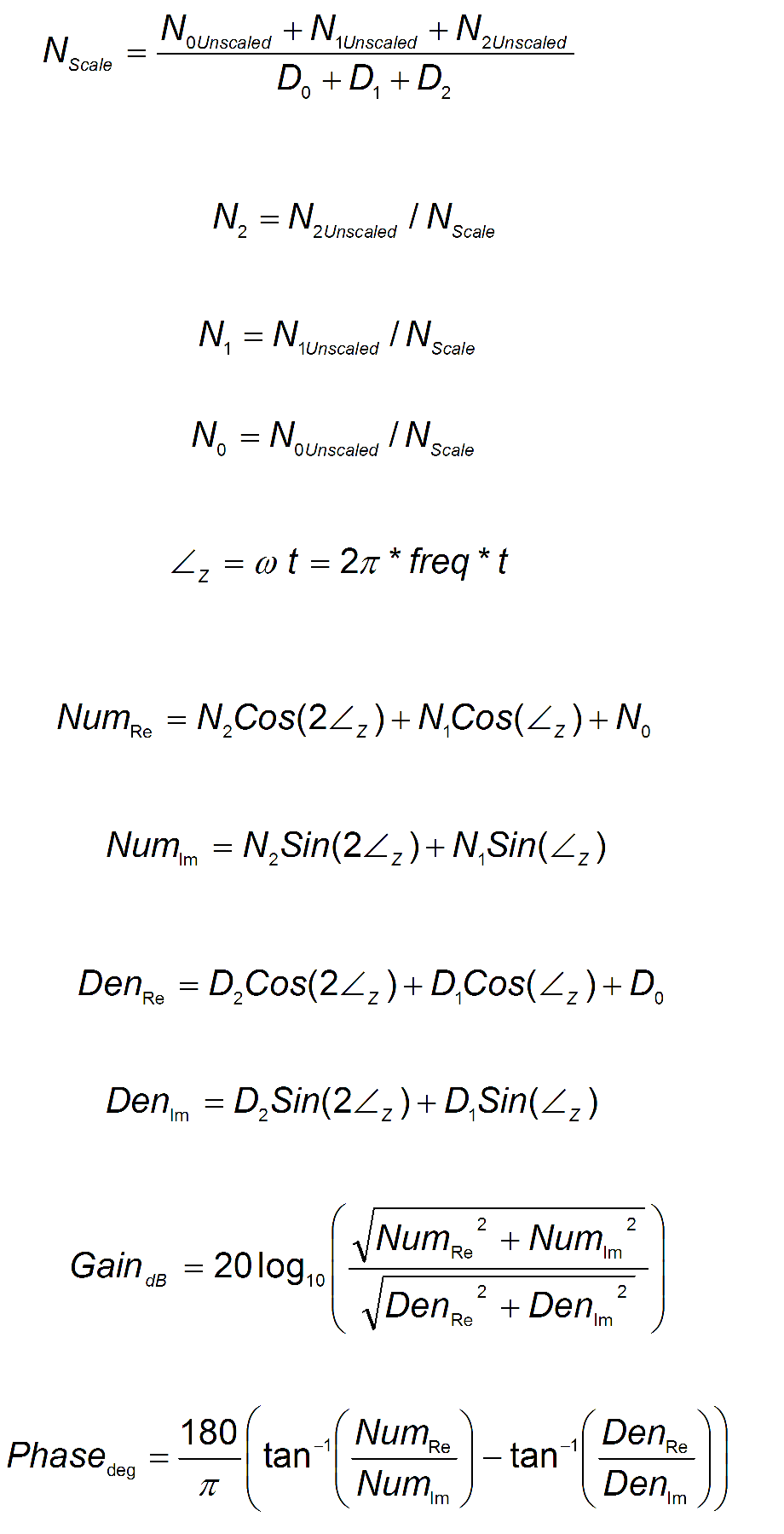
To convert from idealized s-domain behavior to a more realistic z-domain behavior, we convert using a pole / zero transform. To calculate the frequency response for an individual frequency:
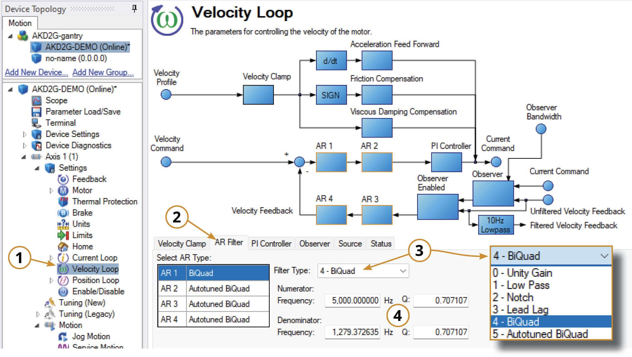
Adjusting BiQuad in the Velocity Loop
To specify a notch filter, you must specify the Numerator and Denominator Frequencies (Hz), along with their associated Q values. To do this, see the following example by clicking on the Velocity Loop:
-
Open the Velocity Loop pane.
-
Open the AR Filter tab and select the AR filter that will function as Notch.
-
Select 4 - BiQuad as the Filter Type.
-
Set the desired Numerator and Denominator Frequencies and Q values.
Adjusting BiQuad (Custom) Using the Manual Tuning Simulator
Within the Velocity Loop section of the Simulation pane, the filter type and values can be entered for AR filters 1-4.
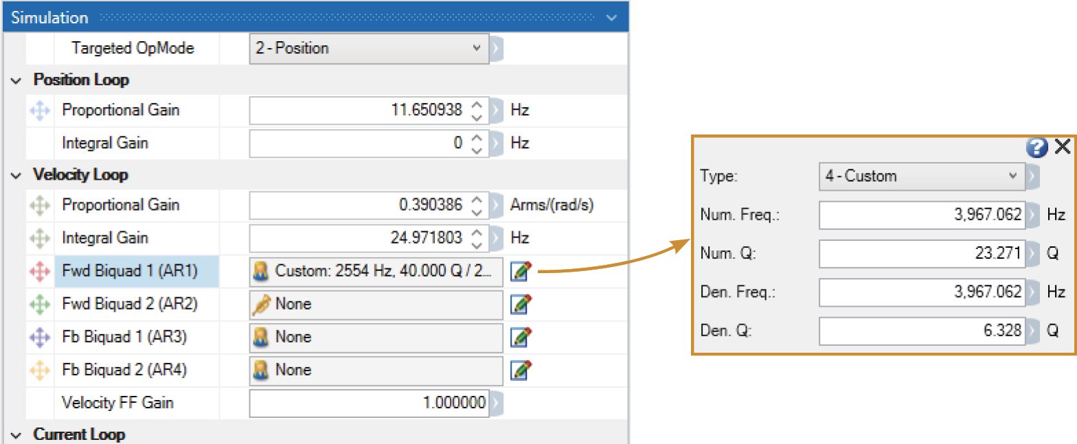
Once the filter type is set to Custom (BiQuad), the Bode Plot Drag+Drop tool may be used to visually adjust the values.
After setting the values within the Simulation pane or using the Drag+Drop sliders, the settings must be written to drive to take effect.


