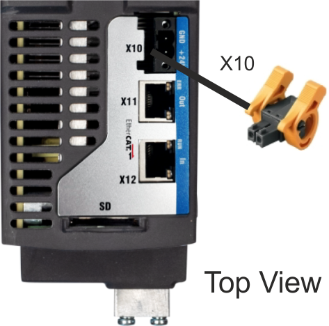
Auxiliary voltage power supply connector X10
The following diagram describes external 24 VDC power supply (PELV). The required supply current rating depends on the use of motor brake (see "Electrical data").
|
|
|
Pin |
Signal | Description |
|---|---|---|
|
1 |
+ 24 V |
+24 VDC supply voltage, PELV |
|
2 |
GND |
Ground for 24 VDC supply voltage, PELV |
For control supply current requirement specifications see section Steady State Control Current per Brake Option.
Fusing
Use 24 VDC supply manufacturer's recommendation for fusing.
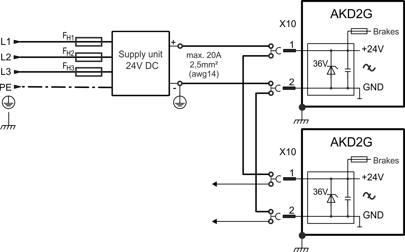
Wiring example 24 VDC supply
Maximum current for one string of daisy-chained X10T connectors is 20 A. The sum of the control currents of the connected drives should not exceed 20 A. With the data given in the table above, you can connect for example:
6 single axis drives, or 4 dual axis drives, or 3 single + 2 dual axis drives.
Wiring example with three phase power supply unit: