


 Homing
Overview
Homing is used to move a motor (connected to a mechanism) to a specific location on the machine, referred to as “home”. This home position is used as the point all subsequent absolute movements are measured from. To start a motion task the axis needs to be homed first.
AKD2G can set the home position using many different combinations of signals, including limit switches (end of travel switches), a dedicated home switch (reference), end stops, encoder z pulses, and the zero angle from single turn feedbacks. AXIS#.HOME.MODE is used to select which homing mode will be used.
All homing modes provide the options of adjusting the acceleration, deceleration, and speed used when searching for the home position. Most modes will finish searching at the new home position, position zero. After the motion to search for the home position has completed you can offset the zero position with AXIS#.HOME.P from the reference point.
Once the reference has been established AXIS#.HOME.DIST allows the motor to be moved away from the reference point. By default AXIS#.HOME.DIST is zero so there will be no extra movement.
Using Homing
The AKD2G includes a variety of homing methods (set with AXIS#.HOME.MODE) to accommodate your machine needs:
| Mode | Description |
|---|---|
|
0 |
Current position |
|
1 |
Find limit switch |
|
2 |
Find limit switch then find zero angle |
|
3 |
Find limit switch then find index |
|
4 |
Find home switch |
|
5 |
Find home switch then find zero angle |
|
6 |
Find home switch then find index |
|
7 |
Find zero angle |
|
8 |
Find end stop |
|
9 |
Find end stop then find zero angle |
|
10 |
Find end stop then find index |
|
11 |
Find index signal, without any precondition |
|
12 |
Find home switch, including end stop detection |
| 13 | Absolute Mode - Use Feedback Position |
| 14 | Reserved |
| 15 | Find next feedback zero position |
| 16 | Find home switch using dual edges |
| 19 | Gantry Homing - Use Master Settings (AXIS2 only) |
-
-
When using any of the methods that use homing switches and limits, please refer to the Input/Output section for proper wiring techniques.
Home Default Window
The Home window allows you to select a homing method and configure homing settings. This window also provides simple controls to start homing and confirm homing success. The view has three sections, Mode, Settings, and Controls.
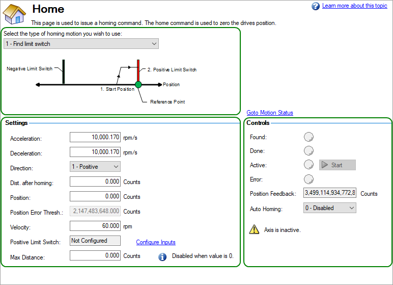
The Mode selection is used choose the desired homing mode. Homing modes are described below in Selecting and Using Homing Modes.
The Settings area contains attributes specific to the homing method selected.
| Element | Description | Parameter |
|---|---|---|
| Acceleration | The acceleration used while homing | AXIS#.HOME.ACC |
| Deceleration | The deceleration used while homing | AXIS#.HOME.DEC |
| Direction | The initial direction for homing | AXIS#.HOME.DIR |
| Distance After Homing | The distance from the found home position the axis should move after home point is found. The default of zero makes the axis move to the found homing position | AXIS#.HOME.DIST |
| Position | The position given to the home position once it is found | AXIS#.HOME.P |
| Position Error Threshold | The position error used for detecting a mechanical stop when using modes 8, 9, 10, or 12. | AXIS#.HOME.PERRTHRESH |
| Velocity | The velocity used while homing | AXIS#.HOME.V |
| Creep Factor | The percentage of the homing speed used while searching for the feedback’s index. This is used by modes 3, 6, 10, 11, and 16. | AXIS#.HOME.CREEPFACTOR |
| Home Switch | Select which digital input will be used as the home switch. This is used by modes 4, 5, 6, 12, and 16. | AXIS#.HOME.SWITCHSOURCE |
| Max Distance | Sets the maximum distance the axis is allowed to move while homing. | AXIS#.HOME.MAXDIST |
| Peak Current | The peak current that will be applied when homing against a mechanical stop. This is used by modes 8, 9, 10, and 12. | AXIS#.HOME.IPEAK |
| Positive Limit Switch | Read-only. This item displays which, if any, digital input is used for a positive limit switch. This is used by modes 2, 3, and 4. | AXIS#.HWLS.POSSOURCE |
| Negative Limit Switch | Read-only. This item displays which, if any, digital input is used for a negative limit switch. This is used by modes 2, 3, and 4. | AXIS#.HWLS.NEGSOURCE |
The Controls area is common to all homing methods. This section allows you to start and stop homing and it provides feedback during and after the homing process.
| Element | Description | Parameter |
|---|---|---|
| Found | Green when the home reference is found. | AXIS#.MOTIONSTAT bit 1 |
| Done | Green when the home move is complete. | AXIS#.MOTIONSTAT bit 2 |
| Active | Green while the axis is homing. | AXIS#.MOTIONSTAT bit 3 |
| Error | Red if homing failed. | AXIS#.MOTIONSTAT bit 4 |
| Position Feedback | The curent position of the axis | AXIS#.PL.FB |
| Auto Homing | Allows the axis to automatically home when first enabled | AXIS#.HOME.AUTOMOVE |
| Start/Stop | Click this button to start or stop the selected homing method | AXIS#.HOME.MOVE and AXIS#.STOP |
Homing Terminology
Retain Homing During Power Cycle
Starting with firmware version 02-01-05-000, the drive automatically saves the home offset and restores the offset when the drive is booted. A homing may still be required to execute motion tasks after rebooting, depending on the feedback used as position loop source (AXIS#.PL.FBSOURCE) and the settings of AXIS#.HOME.MULTITURNMODE and AXIS#.HOME.SINGLETURNMODE (from version 02-10-03).
- When AXIS#.PL.FBSOURCE selects a single turn feedback, the Home Found and Home Done bits in AXIS#.MOTIONSTAT will be restored if AXIS#.HOME.SINGLETURNMODE is set to 1, a Homing move has been completed on the axis at least once, and neither DRV.RSTVAR nor the AXIS#.HOME.CLEAR command has been executed after Homing is complete.
- When AXIS#.PL.FBSOURCE selects a multiturn feedback and AXIS#.HOME.MULTITURNMODE is set to 1, the Home Found and Home Done bits in AXIS#.MOTIONSTAT will always be set and no new homing will have to be done.
- When AXIS#.PL.FBSOURCE selects a multiturn feedback and AXIS#.HOME.MULTITURNMODE is set to 0, the Home Found and Home Done bits in AXIS#.MOTIONSTAT will only be set if a Homing move has been done on the axis at least once and neither the DRV.RSTVAR nor the AXIS#.HOME.CLEAR command has been executed after Homing is complete.
Homing after rebooting is not required once the correct settings for AXIS#.HOME.SINGLETURNMODE or AXIS#.HOME.MULTITURNMODE are completed.
-
- Once the correct settings are in place to restore homing, the drive won’t recognize if the feedback device is changed, and thus will restore the homing state of the previous feedback device to the new feedback device. If a feedback device is changed, the Home settings will now be incorrect and the drive should be re-homed.
Selecting and Using Homing Mode
Mode 0 uses the current position as the reference point. This is the most basic homing method.
The motor does not need to move to find the reference point and the position command AXIS#.PL.CMD and position feedback AXIS#.PL.FB are set equal to AXIS#.HOME.P. By default, AXIS#.HOME.P is zero so the current position will become position zero.
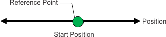
The sequence is:
- The motor does not move.
- The reference point is the current position.
- The actual and command position of the axis are set to AXIS#.HOME.P.
- The motor moves to the position AXIS#.HOME.P + AXIS#.HOME.DIST.
Mode 1 uses the Limit Switch as the reference point. The motor moves to find the limit switch. AXIS#.HOME.DIR is the direction the motor will start moving and selects if the positive or negative limit switch will be the reference point.
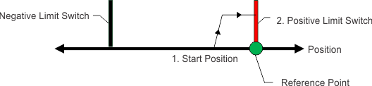
The sequence is:
- The motor starts to move with the direction AXIS#.HOME.DIR.
- The motor stops when the hardware limit switch is detected (its falling edge).
- The motor starts moving in the opposite direction with a velocity reduced by AXIS#.HOME.CREEPFACTOR.
- The reference point is the position when the limit switch is no longer active (its rising edge).
- The actual and command position of the axis are set to AXIS#.HOME.P.
- The motor ramps down to zero velocity.
- The motor moves to the position AXIS#.HOME.P + AXIS#.HOME.DIST.
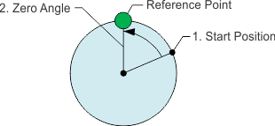
Mode 2 uses the Zero Angle from the feedback nearest the Limit Switch as the reference point. This mode is like mode 1 with an additional step to use the zero angle from the feedback. AXIS#.HOME.DIR is the direction the motor will start moving and selects if the positive or negative limit switch will be the reference point.
This mode cannot be used with incremental and sine encoders (FB#.SELECT is 10, 11, 20 or 21). These feedbacks always power on with a position of zero, making the zero angle likely to be different each power cycle.
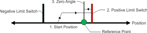
The sequence is:
- The motor starts to move with the direction AXIS#.HOME.DIR.
- The motor stops when the hardware limit switch is detected (its falling edge).
- The motor starts moving in the opposite direction with a velocity reduced by AXIS#.HOME.CREEPFACTOR.
- When the limit switch is no longer active (its rising edge) the reference point is the next zero angle the axis will pass.
- The actual and command position of the axis are set to AXIS#.HOME.P plus the distance the zero angle is away from the limit switch.
- The motor ramps down to zero velocity.
- The motor moves to the position AXIS#.HOME.P + AXIS#.HOME.DIST.
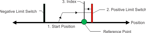
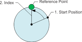
Mode 3 uses the Index Pulse nearest the Limit Switch as the reference point. This mode is like mode 1 with an additional step to find the first index pulse after the limit switch has been found. AXIS#.HOME.DIR is the direction the motor will start moving and selects if the positive or negative limit switch will be the reference point.
This mode can only be used with feedback devices that have an index pulse, such as incremental encoders and sine encoders with an index channel (FB#.SELECT is 10, 11, 20, 21). If the feedback selected does not have an index pulse a warning “6025 : Homing and feedback mismatch” will be reported.
The sequence is:
- The motor starts to move with the direction AXIS#.HOME.DIR.
- The motor stops when the hardware limit switch is detected (its falling edge).
- The motor starts moving in the opposite direction with a velocity reduced by AXIS#.HOME.CREEPFACTOR.
- The motor keeps moving until the limit switch is no longer active (its rising edge).
- The motor ramps continues at the velocity reduced by AXIS.HOME.CREEPFACTOR searching for the index pulse.
- The reference point is the position when the first index pulse from the feedback is detected.
- The actual and command position of the axis are set to AXIS#.HOME.P.
- The motor ramps down to zero velocity.
- The motor moves to the position AXIS#.HOME.P + AXIS#.HOME.DIST.
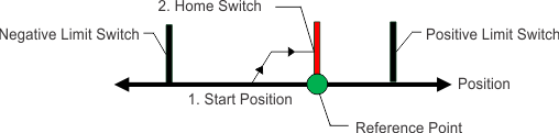
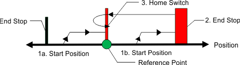
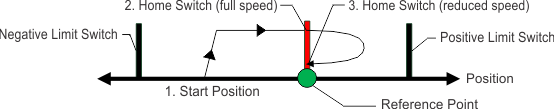
Mode 4 uses the Home Switch as the reference point. The motor moves to find the home switch. AXIS#.HOME.DIR is the direction the motor will start moving to find the home switch.
If the Limit Switches are hit before the home switch, the motor will reverse and continue searching in the opposite direction. If both limit switches are hit, the homing will fail and warning 6012 “Home switch not found” is generated.
The sequence is:
- The motor starts to move with the direction AXIS#.HOME.DIR.
- If a limit switch is hit (its falling edge) the motor will stop and start moving in the opposite direction.
- The reference point is position when the rising edge of the home switch is detected.
- The actual and command position of the axis are set to AXIS#.HOME.P.
- The motor ramps down to zero velocity.
- The motor moves to the position AXIS#.HOME.P + AXIS#.HOME.DIST.
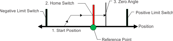
Mode 5 uses the Zero Angle from the feedback nearest the Home Switch as the reference point. This mode is like mode 4, with an additional step to use the zero angle from the home switch as the reference point. The motor moves to find the home switch. AXIS#.HOME.DIR is the direction the motor will start moving to find the home switch.
This mode cannot be used with incremental and sine encoders (FB#.SELECT is 10, 11, 20 or 21). These feedbacks always power on with a position of zero, making the zero angle likely to be different each power cycle.
If the Limit Switch are hit before the home switch, the motor will reverse and continue searching in the opposite direction. If both limit switches are hit, the homing will fail and warning 6012 “Home switch not found” is generated.
The sequence is:
- The motor starts to move with the direction AXIS#.HOME.DIR.
- If a limit switch is hit (its falling edge) the motor will stop and start moving in the opposite direction searching for the home switch. The axis will move past the home switch and reverse again to approach always approach the home switch from the same direction.
- When the home switch is passed in the direction AXIS#.HOME.DIR the reference point is the next zero angle from the feedback.
- The actual and command position of the axis are set to AXIS#.HOME.P plus the distance the zero angle is away from the home switch.
- The motor ramps down to zero velocity.
- The motor moves to the position AXIS#.HOME.P + AXIS#.HOME.DIST.
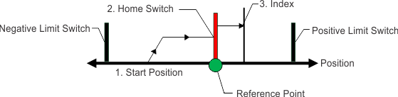
Mode 6 uses the first index pulse after passing the Home Switch as the reference point. This mode is like mode 4 with an additional steps to find the index pulse. AXIS#.HOME.DIR is the direction the motor will start moving to find the home switch.
If the Limit Switches are hit before the home switch, the motor will reverse and continue searching in the opposite direction. If both limit switches are hit, the homing will fail and warning 6012 “Home switch not found” is generated.
This mode can only be used with feedback devices that have an index pulse, such as incremental encoders and sine encoders with an index channel (FB#.SELECT is 10, 11, 20, 21). If the feedback selected does not have an index pulse a warning “6025 : Homing and feedback mismatch” will be reported.
The sequence is:
- The motor starts to move with the direction AXIS#.HOME.DIR.
- If a limit switch is hit (its falling edge) the motor will stop and start moving in the opposite direction searching for the home switch. The axis will move past the home switch and reverse again to approach always approach the home switch from the same direction.
- When the home switch is passed in the direction AXIS#.HOME.DIR the motor decelerates to a reduced velocity, AXIS#.HOME.CREEPFACTOR, searching for the index pulse.
- The reference point is the position when the first index pulse from the feedback is detected.
- The actual and command position of the axis are set to AXIS#.HOME.P plus the distance the zero angle is away from the home switch.
- The motor ramps down to zero velocity.
- The motor moves to the position AXIS#.HOME.P + AXIS#.HOME.DIST.
Mode 7 uses the Zero Angle from the feedback as the reference point. AXIS#.HOME.DIR indicates if the position of the reference point to the current position.
This mode cannot be used with incremental and sine encoders (FB#.SELECT is 10, 11, 20 or 21). These feedbacks always power on with a position of zero, making the zero angle likely to be different each power cycle.
The sequence is:
- The reference point is immediately found using as zero angle from the feedback.
- The actual and command position of the axis are set to AXIS#.HOME.P plus the distance the zero angle is away from the current position.
- The motor moves to the position AXIS#.HOME.P + AXIS#.HOME.DIST.
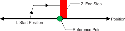
Mode 8 uses the position of the End Stop as the reference point. The end stop is detected by moving until the position error exceeds AXIS#.HOME.PERRTHRESH.
AXIS#.HOME.IPEAK can be used to limit the force applied against to the end stop.
-
- Be sure to choose the direction appropriately to move off of the stop if using the distance offset.
The sequence is:
- The motor starts to move with the direction AXIS#.HOME.DIR.
- The reference point is the position when the position error exceeds AXIS#.HOME.PERRTHRESH.
- The motor moves to the position AXIS#.HOME.P + AXIS#.HOME.DIST.
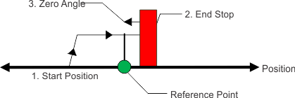
Mode 9 uses the position of last Zero Angle before the End Stop as the reference point. The end stop is detected by moving until the position error exceeds AXIS#.HOME.PERRTHRESH. This mode is like mode 8 with an additional step to use the zero angle from the feedback.
AXIS#.HOME.IPEAK can be used to limit the force applied against to the end stop.
This mode cannot be used with incremental and sine encoders (FB#.SELECT is 10, 11, 20 or 21). These feedbacks always power on with a position of zero, making the zero angle likely to be different each power cycle.
The sequence is:
- The motor starts to move with the direction AXIS#.HOME.DIR.
- When the position error exceeds AXIS#.HOME.PERRTHRESH the motor stops.
- The reference point is the zero angle before the end stop was detected.
- The motor moves to the position AXIS#.HOME.P + AXIS#.HOME.DIST.
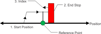
Mode 10 uses the Index Pulse nearest the End Stop as the reference point. The end stop is detected by moving until the position error exceeds AXIS#.HOME.PERRTHRESH. This mode is like mode 8 with an additional step to find the index pulse.
AXIS#.HOME.IPEAK can be used to limit the force applied against to the end stop.
This mode can only be used with feedback devices that have an index pulse, such as incremental encoders and sine encoders with an index channel (FB#.SELECT is 10, 11, 20, 21). If the feedback selected does not have an index pulse a warning “6025 : Homing and feedback mismatch” will be reported.
The sequence is:
- The motor starts to move with the direction AXIS#.HOME.DIR.
- When the position error exceeds AXIS#.HOME.PERRTHRESH the motor stops.
- The motor starts moving in the opposite direction with a reduced velocity, AXIS#.HOME.CREEPFACTOR, searching for the index pulse.
- The reference point is the position when the first index pulse from the feedback is detected.
- The motor moves to the position AXIS#.HOME.P + AXIS#.HOME.DIST.
Mode 11 uses next Index Pulse from the feedback as the reference position.
This mode can only be used with feedback devices that have an index pulse, such as incremental encoders and sine encoders with an index channel (FB#.SELECT is 10, 11, 20, 21). If the feedback selected does not have an index pulse a warning “6025 : Homing and feedback mismatch” will be reported.
The sequence is:
- The motor starts to move with the direction AXIS#.HOME.DIR.
- The motor is searching for the index pulse at with a reduced velocity, AXIS#.HOME.CREEPFACTOR.
- If the limit switch is hit (its falling edge) before the index pulse, the motor changes and searches in the opposite direction.
- The reference point is the position when the next index pulse from the feedback is detected.
- The motor moves to the position AXIS#.HOME.P + AXIS#.HOME.DIST.
Mode 12 uses the Home Switch as the reference point. The motor moves to find the home switch. AXIS#.HOME.DIR is the direction the motor will start moving to find the home switch.
If the end stops are hit before the home switch the motor will reverse and continue searching in the opposite direction. The end stop is detected by moving until the position error exceeds AXIS#.HOME.PERRTHRESH.
The sequence is:
- The motor starts to move with the direction AXIS#.HOME.DIR.
- If an end stop is hit (the position error exceeds AXIS#.HOME.PERRTHRESH) the motor will stop and start moving in the opposite direction.
- The reference point is position when the rising edge of the home switch is detected.
- The actual and command position of the axis are set to AXIS#.HOME.P.
- The motor ramps down to zero velocity.
- The motor moves to the position AXIS#.HOME.P + AXIS#.HOME.DIST.
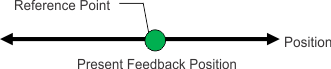
Mode 13 uses the unmodified position from the feedback device. This mode does not perform any movement.
When the drive is powered on using a multi-turn, absolute feedback device, the axis will start homed and no further homing is required. This mode is provided for when you have changed the feedback and do not want to power cycle the drive to start using the new position data.
Single-turn absolute devices can also utilize this mode if they are used in applications like a rotary index table where the entire range is within 360 degrees.
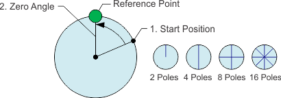
Mode 15 uses the Zero Angle from the feedback as the reference point. AXIS#.HOME.DIR indicates if the position of the reference point to the current position. Mode 15 is like mode 7 (find zero angle), however, if the feedback device has more than 1 pole pair (2 poles), the motor will home to the next pole pair. The number of resolver poles is set with FB#.POLES .
If the feedback device has 2 poles (1 pole pair) then this mode will operate exactly the same as homing mode 7.
This mode cannot be used with incremental and sine encoders (FB#.SELECT is 10, 11, 20 or 21). These feedbacks always power on with a position of zero, making the zero angle likely to be different each power cycle.
The sequence is:
- The reference point is immediately found using as zero angle from the feedback.
- The actual and command position of the axis are set to AXIS#.HOME.P plus the distance the zero angle is away from the current position.
- The motor moves to the position AXIS#.HOME.P + AXIS#.HOME.DIST.
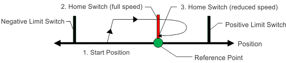
Mode 16 uses the Home Switch as the reference point. The motor moves to find the home switch. AXIS#.HOME.DIR is the direction the motor will start moving to find the home switch. Once the switch is found, it will approach the home switch from the other direction at a reduced speed for increased accuracy.
If the Limit Switches are hit before the home switch, the motor will reverse and continue searching in the opposite direction. If both limit switches are hit, the homing will fail and warning 6012 "Home switch not found" is generated.
This homing mode is similar to homing mode 4, but is better for applications which home at high velocity and require high accuracy.
The sequence is:
- The motor starts to move with the direction AXIS#.HOME.DIR.
- If a limit switch is hit (its falling edge) the motor will stop and start moving in the opposite direction.
- The motor stops when the home switch is detected (its rising edge).
- The motor starts moving in the opposite direction at a reduced velocity set by AXIS#.HOME.CREEPFACTOR.
- The reference point is when the home switch is no longer active (its falling edge).
- The actual and command position of the axis are set to AXIS#.HOME.P.
- The motor ramps down to zero velocity.
- The motor moves to the position AXIS#.HOME.P + AXIS#.HOME.DIST.
This mode has Axis 2 follow Axis 1 in homing. Axis 2 will move at the same speed and acceleration, and will move to the same target position using the same trigger source. The drawing indicates the homing mode selected on Axis 1.
-
- This mode is only available on AKD2G drives, and is applicable to Axis 2. This mode requires that Axis 2 uses command source 4(AXIS#.CMDSOURCE = 4).
This mode uses all of the settings defined from Axis 1 and the signals from that axis. This means you can trigger Axis 2 homing from Axis 1 index pulse or mechanical zero.
-
-
- Homing to a hard stop
Homing to a hard stop is independent in any mode. This means each axis will find its own hard stop. - Modes which home to a hard stop and then look for some signal
Homing modes which include a hard stop and then an additional step are not supported at this time. This includes Home Modes 9, 10 and 12. - Setting any AXIS2.HOME parameter will be saved while command mode 19 is selected on Axis 2. This saved setting is not active until a command mode other than 19 is used. Reading back a homing parameter from Axis 2 while command mode 19 is selected will return the parameter that is currently active from Axis 1.
- Homing to a hard stop
Related Parameters and Commands


