


Wiring
|
|
|

General
|
|
There is a danger of serious personal injury or death by electrical shock or electrical arcing.
|


|
|
|

Mating connectors
|
|
|
| # |
Description |
Type |
Max. Cross |
|---|---|---|---|
|
X1/2 |
Motor, two wire feedback, holding brake |
Connector, 4 pol. power |
10 mm², 8 awg |
|
Connector, 4 pol. signal |
0.5 mm², 21 awg |
||
|
X3/X3T |
Mains power, regen resistor, DC-Bus |
Connector or T-type, 8 pol. |
6 mm², 10 awg |
|
X3A/X3B |
Mains power, regen resistor, DC-Bus |
Connector, 4 pol. power |
6 mm², 10 awg |
|
X4 |
Second brake |
Connector, 3 pol. |
1.5 mm², 16 awg |
|
X5 |
Second feedback, two wire |
Connector, 3 pol. |
1.5 mm², 16 awg |
|
X10T |
24V power supply |
T-type Connector, 2 pol. |
2.5 mm², 14 awg |
|
X11/12 |
EtherNet Fieldbus |
RJ45 |
0.5 mm², 21 awg |
|
X13/14 |
CAN In/Out |
RJ25 |
0.5 mm², 21 awg |
|
X20 |
Service Port |
RJ45 |
0,5 mm², 21 awg |
|
X21 |
I/O control signals |
Connector, 2x11 pol. |
1.5 mm², 16 awg |
|
X22 |
I/O control signals |
Connector, 2x10 pol. |
1.5 mm², 16 awg |
|
X23 |
Conventional feedback models |
SubD 15pol. HD (female) |
0.5 mm², 21 awg |
Cable and Wire Requirements
Cable material
For information on the chemical, mechanical, and electrical characteristics of the cable
|
|
To reach the maximum permitted cable length, you have to use cable material with the following capacitance requirements: |
- Motor power cable: less than 150 pF/m (phase core to shield capacitance)
- Motor Feedback cable: less than 120 pF/m (signal core to shield capacitance)
- Hybrid motor cable:
- less than 120 pF/m (phase core/core capacitance)
- less than 210 pF/m (phase core/shield capacitance)
- less than 120 pF/m (signal core/core capacitance)
- less than 210 pF/m (signal core/shield capacitance)
- BUS Element: 45 pF/m @ 800kHz & charact. wave resistance 110±10Ω @ 10MHz
Cable length
|
|
|
Motor cables (X1, X2, X4, X5, X23, X41)
Length of motor power cables, feedback cables and motor brake cables is equal.
|
AKM2G |
AKM |
||||
|---|---|---|---|---|---|
|
Performance Line Cables |
Performance Line Cables |
Value Line Cables |
|||
|
Feedback |
Max. Length [m] |
Feedback |
Max. Length [m] |
Feedback |
Max. Length [m] |
|
SFD-3/SFD-M |
50 |
All |
25 |
All |
12 |
|
DSL |
25 |
||||
|
EnDat 2.2 |
25 |
||||
|
Resolver |
50 |
||||
I/O cables (X21, X22)
|
|
Maximum distance for unshielded I/O lines is 3m inside the cabinet. If the I/O cable leaves the cabinet, it must be EMC shielded. |
T-Connector wiring
If you use mating T-connectors for 24 VDC supply, mains voltage supply and DC-Bus link, you have to prepare the connecting cables with wire end ferrules.
You can prepare cables with cross-section 2.5mm² (up to to 6mm²) with a uniform length of 170mm, if the modules are lined up close together.
Use wire end ferrules with plastic collars, for example 2.5mm² x 17mm.
Cable cross sections and requirements
The tables below describe the recommended interface cross sections and cable requirements related to AKD2G in accordance with IEC 60204.
|
Power Cables |
Cross Section |
Remarks | ||
|---|---|---|---|---|
|
EU |
US |
|||
|
Mains supply |
1x3 A: |
1.5 mm² |
14 awg |
600 V rated ,minimum 75°C |
|
24 V supply |
max. |
2.5 mm² |
14 awg |
Single core Flexible Class 5 |
|
DC bus link, |
3/6 A: |
1.5 mm² |
14 awg |
1000 V rated, min. 75°C, shielded for lengths >0.20 m |
|
I/O cables |
||||
|
Analog I/Os |
min. |
0.25 mm² |
24 awg |
shielded twisted pairs |
|
Digital I/Os |
|
0.5 mm² |
20 awg |
single core |
Motor power cable (power) & motor combination cable (power & brake)
|
Cross Section [mm] |
Current Carrying |
Remarks |
|
|---|---|---|---|
|
Cable |
Combi Cable |
||
|
(4x1) |
(4x1.0+(2x0.75)) |
0A < I0rms ≤ 10.1A |
1000 V Rated, 80°C Current carrying capacity The brackets (...) show |
|
(4x1.5) |
(4x1.5+(2x0.75)) |
10.1A < I0rms ≤ 13.1A |
|
|
(4x2.5) |
(4x2.5+(2x1.0)) |
13.1A < I0rms ≤ 17.4A |
|
|
(4x4) |
(4x4.0+(2x1.0)) |
17.4A < I0rms ≤ 23A |
|
|
(4x6) |
(4x6.0+(2x1.0)) |
23A < I0rms ≤ 30A |
|
Motor feedback cable
|
Type |
Cross Section [mm] |
Remarks |
|---|---|---|
|
Resolver |
(4x2x0.25) |
300 V rated, 80°C Shielded twisted pairs The brackets (...) show |
|
EnDat 2.1, BiSS B |
(6x2x0.25) |
|
|
HIPERFACE |
(5x2x0.25) |
|
|
EnDat 2.2, BiSS C |
(5x2x0.25) |
|
|
SFD |
(3x2x0.25) |
|
|
Comcoder |
(8x2x0.25) |
Motor hybrid cable
|
Type |
Cross Section [mm] |
Current Carrying |
Remarks |
|---|---|---|---|
|
SFD-M/SFD-3/HDSL |
(4x1.0+(2x0.34)+(2x0.75)) |
0A < I0rms ≤ 10.1A |
1000 V rated, 80 °C Current carrying capacity acc. to IEC 60204-1:2006 Table 6, Column B2 4 power lines & |
|
SFD-M/SFD-3/HDSL |
(4x1.5+(2x0.34)+(2x0.75)) |
10.1A < I0rms ≤ 13.1A |
|
|
SFD-M/SFD-3/HDSL |
(4x2.5+(2x0.34)+(2x1.0)) |
13.1A < I0rms ≤ 17.4A |
|
|
SFD-M/SFD-3/HDSL |
(4x4.0+(2x0.34)+(2x1.0)) |
17.4A < I0rms ≤ 23A |
|
|
SFD-M/SFD-3/HDSL |
(4x6.0+(2x0.34)+(2x1.0)) |
23A < I0rms ≤ 30A |
|
|
EnDat 2.2 |
(4x1.5+(2x0.75)+(2x2x0.14+2x0.25)) |
10.1A < I0rms ≤ 13.1A |
|
|
EnDat 2.2 |
(4x4.0+(2x1.0)+(2x2x0.14+2x0.25)) |
17.4A < I0rms ≤ 23A |
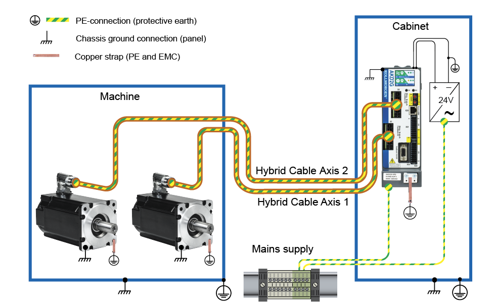
Protective Earth Connection
Protective Earth connection of the system components is a safety measure per IEC 60204. Ensure the proper grounding of all components with the PE rail in the control cabinet as reference potential. Connect each ground individually with the intended grounding cable (neutral point connection).
The leakage current from AKD2G against PE is more than 3.5 mA. In accordance with EN 61800-5-1, the PE connection must therefore either be double implemented or a connection cable with >10 mm² cross-section used.
In order to keep the impedance as low as possible, we recommend a copper earthing strap for the PE connection on the PE block.
|
|
|
|
|
For the use of residual current protective devices (RCD), refer to (see "Residual current protective device (RCD)"). |