OSSD
Test pulses on safe digital inputs (SIN1 to SIN4)

|
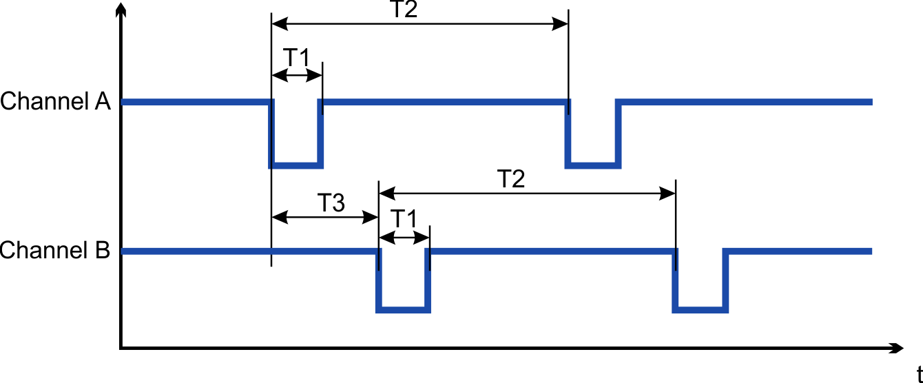
The Safety Controller used must be compatible with OSSD (Output Switching Signal Device) according to IEC 61496-1. |
Safety controllers check their outputs periodically during normal operation. Their self-test processes create pulses to the safe inputs of the drive.

|
Timing |
Min |
Max |
|---|---|---|
|
T1 |
150 µs |
1 ms |
|
T2 |
100 ms |
1 s |
|
T3 |
> T1 (non-overlapping) |
|

|
Test pulses with 150 µs ≤ T1 ≤ 1 ms and T2 ≥ 100 ms will not have any influence on the safety function. Test pulses, which are outside of this specification, will switch the safety function but will not create a dangerous situation. The SMM software enters the I/O Failure State (fault reaction time ≤ 2ms)
With Safety Option 1 test pulses are ignored. |
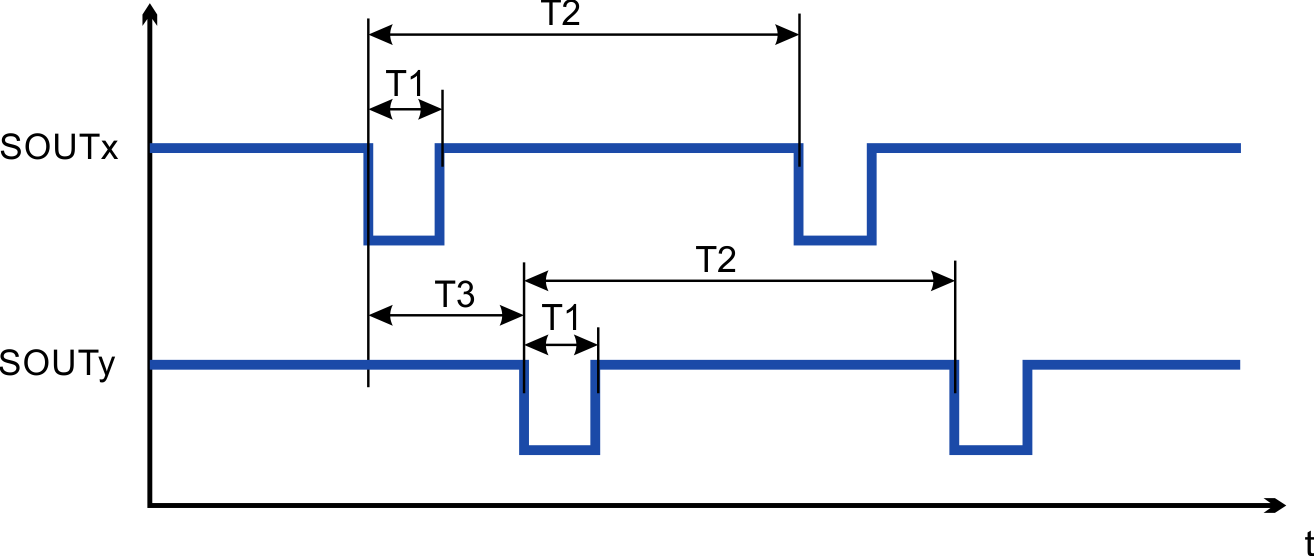
Test pulses on safe digital outputs (SOUT1 to SOUT4)
The safe digital outputs can be used as 24 V source voltage to be switched by an external safety relay to STO inputs.

|
Timing |
Min |
Max |
|---|---|---|
|
T1 |
450 µs |
550 µs |
|
T2 |
810 ms |
990 ms |
|
T3 |
> T1 (non-overlapping) |
|

|
The output test pulses are compatible with the safe digital input requirements. There is only one test pulse on all four outputs at a time. They do not overlap each other. Be sure to use a force-guide relay, converter, or controller that does not respond to these test pulses. |


