


 Brake
Brake
Description
Each axis can have at least one brake attached that will lock the motor shaft into place and prevent motion. This is useful to keep the motor shaft from moving while disabled and the drive cannot hold the motor position.
-
- Brakes are generally meant to hold position, not stop the motor. Care should be taken in configuring the associated brake parameters such that the brake is not used to stop the motor often. Doing so will damage the motor and/or brake hardware.
There are up to two brake connectors on the AKD2G. Each brake can be configured one per axis, or they can both be set to one axis. When the axis enables or disables the brake(s) assigned to that axis will be commanded to be released or applied accordingly unless the command is manually overridden.
To configure a brake on an axis, a combination of keywords are used:
| Keyword | Description |
|---|---|
| BRAKE#.AXIS | Configures which brake connector the axis controls. |
| AXIS#.MOTOR.BRAKE | Configures whether the axis has a brake attached. |
| AXIS#.MOTOR.TBRAKETO | Sets the time to wait for axis to stop before applying the brake. |
| AXIS#.MOTOR.BRAKEIMM | Sets whether to wait for the axis to stop when disabling in normal instances. |
| AXIS#.MOTOR.TBRAKERLS | The amount of time before the brake should release. |
| AXIS#.MOTOR.TBRAKEAPP | The amount of time before the brake should apply. |
| AXIS#.MOTOR.BRAKECONTROL | Allows manual control of the brakes assigned to this axis. |
| BRAKE#.STATE | The current state of the brake. |
| The velocity threshold that the drive will consider the motor shaft as stopped and the brake can be applied . | |
| AXIS#.DISMODE |
The action taken by the drive when disabling. This affects when the brake gets applied before the power stage is disabled. |
Reference
| Element | Description | Parameter |
|---|---|---|
| Usage |
Configures whether the axis has a brake attached. 0 - Not Used 1 - Used. If this item is selected the Configuration and Override tabs are available. 100 - Used - Fault ignored. If this item is selected the Configuration and Override tabs are available. |
AXIS#.MOTOR.BRAKE |
| Brake # State | The current state of the brake.This item is only visible if a brake is associated with this axis - see Hardware Configuration for more information. | BRAKE#.STATE |
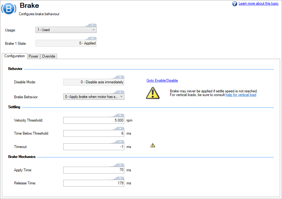
Brake Configuration Tab
| Element | Property | Description | Parameter |
|---|---|---|---|
| Behavior | Disable Mode |
The action taken by the drive when disabling. This affects when the brake gets applied before the power stage is disabled. This is set from the Enable/Disable view. |
AXIS#.DISMODE |
| Brake Behavior |
Sets whether to wait for the axis to stop when disabling in normal instances.
|
AXIS#.MOTOR.BRAKEIMM | |
| Settling | Velocity Threshold | The velocity threshold for the zero velocity detection. | |
| Time Below Threshold |
The time value for the drive velocity to be within AXIS#.ZEROV before the drive disables. |
||
| Timeout | Sets the time to wait for axis to stop before applying the brake. To disable the timer, set the value to -1 (default). |
AXIS#.MOTOR.TBRAKETO | |
| Brake Mechanics | Apply Time | The amount of time before the brake should apply. | AXIS#.MOTOR.TBRAKEAPP |
| Release Time | The amount of time before the brake should release. | AXIS#.MOTOR.TBRAKERLS |
Brake Power Tab
When power saving mode is enabled, full voltage is used to initiate release of brake. After waiting AXIS#.MOTOR.TBRAKERLS milliseconds for brake to mechanically release, an additional delay of AXIS#.MOTOR.BRAKEPOWERDELAY milliseconds waits for brake to electrically stabilize before voltage is reduced to AXIS#.MOTOR.BRAKEPOWERLOW.
| Property | Description | Parameter |
|---|---|---|
| Power Saving | This option controls whether full voltage is used to control the brake (Disabled), or whether Power Saving will be used (Enabled). | AXIS#.MOTOR.BRAKEPOWERSAVING |
| Power Saving Voltage | The low voltage used for brake power saving. | AXIS#.MOTOR.BRAKEPOWERLOW |
| Time to Low Voltage | Time to wait after applying full voltage before dropping to low voltage. | AXIS#.MOTOR.BRAKEPOWERDELAY |
-
-
This parameter is automatically configured for Kollmorgen motors when AXIS#.MOTOR.AUTOSET = 1 and motor memory version is 0.4 or greater. This parameter can be modified while AXIS#.MOTOR.AUTOSET = 1 if its AXIS#.MOTOR.DISAUTOSET index = 1.
Brake Override Tab
Typically brakes are applied automatically, as needed. This tab provides a manual override of brake control. There are three buttons which control the brake behavior.
- Automatic: Default behavior
- Force Apply: Cause the brake to be applied
- Force Release. Cause the brake to be released.
-
- Overriding brake behavior may create unsafe situations and/or damage.
-
-
When SBC is configured and becoming active, the brake behavior is overriden by safety and applied accordingly.