


 Current Loop
Overview
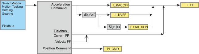
The current loop controls the production of current on each axis. The parameters that govern the current loop are shown in the Current Loop view. The various types of tuning for the drive adjust these parameters automatically, so you normally do not need to adjust the current loop parameters in the current loop screen. The Current Loop view includes an active block diagram. If you click on a block in the diagram, the appropriate tab opens below.
The view below (with Velocity Command and Coulomb Friction Comp.) is enabled if you change the mode from Torque mode to Position mode or Velocity mode.
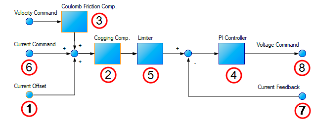
The blocks highlighted above are associated with the following tabs in the Current Loop view:
-
Blocks 1, 2, 3: Compensation Tab
-
Block 4: PI Controller Tab
-
Block 5:Limiter Tab
-
Block 6, 7, 8: Status Tab
-
Source Tab does not have an associated block but is accessible in the Current Loop view.
Compensation Tab
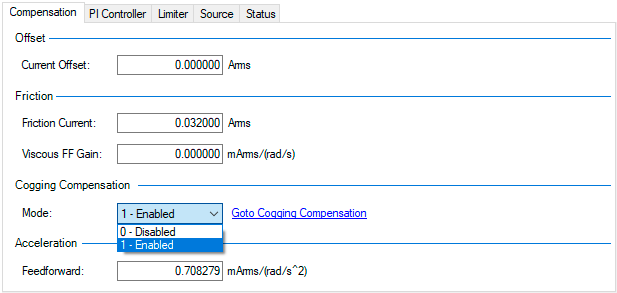
Items found here are a part of blocks #1, #2, and #3 above.
| Element | Property | Description | Parameter |
|---|---|---|---|
| Offset | Current Offset | A constant current command added to compensate for gravity. | AXIS#.IL.OFFSET |
| Friction | Friction Current | This is a friction compensation value. | AXIS#.IL.FRICTION |
| Viscous FF Gain | Current loop velocity feed-forward gain. | AXIS#.IL.KVFF | |
| Cogging Compensation | Mode | Removes the effects of cogging (magnetic forces) between the motor's permanent magnets and windings and repeatable artifacts from bearings, leadscrews, and other mechanical components. | AXIS#.IL.COMPTABLE.ENABLE |
| Acceleration | Feedforward | Sets the gain for the acceleration feedforward (a scaled second derivative of the position command is added to the current command value) | AXIS#.IL.KACCFF |
PI Controller Tab
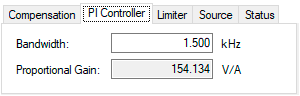
Items found here are calculated in block #4 above (Also see Current Loop )
| Property | Description | Parameter |
|---|---|---|
| Bandwidth | Sets the current loop bandwidth. | AXIS#.IL.BW |
| Proportional Gain | Gets the proportional gain of the q-component of the PI regulator. This is a read-only value. | AXIS#.IL.KP |
Limiter Tab
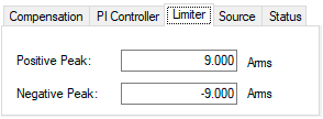
Items found here are calculated in block #5 above
| Property | Description | Parameter |
|---|---|---|
| Positive Peak | Sets the positive user (application-specific) current limit. | AXIS#.IL.LIMITP |
| Negative Peak | Sets the negative user (application-specific) current limit. | AXIS#.IL.LIMITN |
Source Tab
Feedback Selection
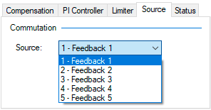
| Element | Property | Description | Parameter |
|---|---|---|---|
| Commutation | Source | Tells the drive which feedback the Current Loop is using for commutation. | AXIS#.IL.FBSOURCE |
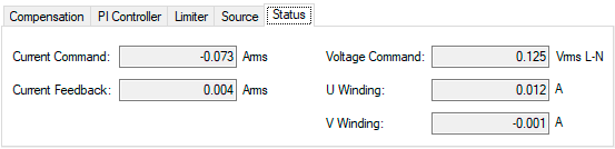
Status Tab
Items found here are calculated in blocks #6, #7, #8 above
| Property | Description | Parameter |
|---|---|---|
| Current Command | Reads the value of the q-component current command. | AXIS#.IL.CMD |
| Current Feedback | Reads the actual value of the q-component current. | AXIS#.IL.FB |
| Voltage Command | Reads the output of the q-component PI regulator. | AXIS#.IL.VCMD |
| U Winding | Reads the sigma-delta measured current in the U-winding of the AXIS#.MOTOR. | AXIS#.IL.IUFB |
| V Winding | Reads the sigma-delta measured current in the V-winding of the AXIS#.MOTOR. | AXIS#.IL.IVFB |
Related Parameters