


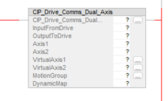
CIP_Drive_Comms AOI
The CIP_Drive_Comms AOI is used to initiate and manage the communications for an axis. It also provides an array structure for holding the Dynamically Mapped data (if applicable).
Compatibility
The CIP_Drive_Comms AOI is only compatible with AKD2G-SPI drives when used with Motion Supported PLCs with Studio 5000 and the CIP Sync connection.
Required Command Source and Operation Mode
- AXIS#.CMDSOURCE = Fieldbus
- AXIS#.OPMODE = Position
The CIP_Drive_Comms AOI is always enabled in the Ladder routine under IOTask > IOProgram by the AOI’s Enable In being tied to the left rail.
- It is executed by the IOTask configured to trigger and execute on the Motion Group Execution trigger with a Priority of 1.
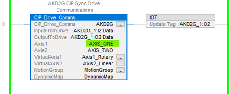
- The instruction is used in tandem with the Studio 5000 IOT instruction.
- See Example of Usage/Programming Guidelines.
The CIP_Drive_Comms AOI fields Axis1 and Axis2 are declared as axis names that are used in the Kollmorgen provided supplementary CIP Axis AOIs’ Axis field.
- The InputFromDrive and OutputToDrive entries bind the data exchange between the:
- AKD2G (declared as a module under Ethernet in the Controller Organizer) for both the CIP Sync Command Assembly and
- CIP Sync Response Assembly to the axis names in the CIP_Drive_Comms instruction (Axis1 and Axis2 field entries).
Structures in the Controller Tags are created when the Axis1 and Axis2 tag names are declared.
- These names are then used with all other Kollmorgen supplementary AOIs which require an Axis field entry.
- This is so any AOIs used with a given axis are correlated to the CIP_Drive_Comms AOI.
This example shows how an AOI is codependent on the CIP_Drive_Comms AOI.
Figure 1: CIP_Drive_Comms AOI Flow Co-dpendency
Figure 1 Callouts Explanation
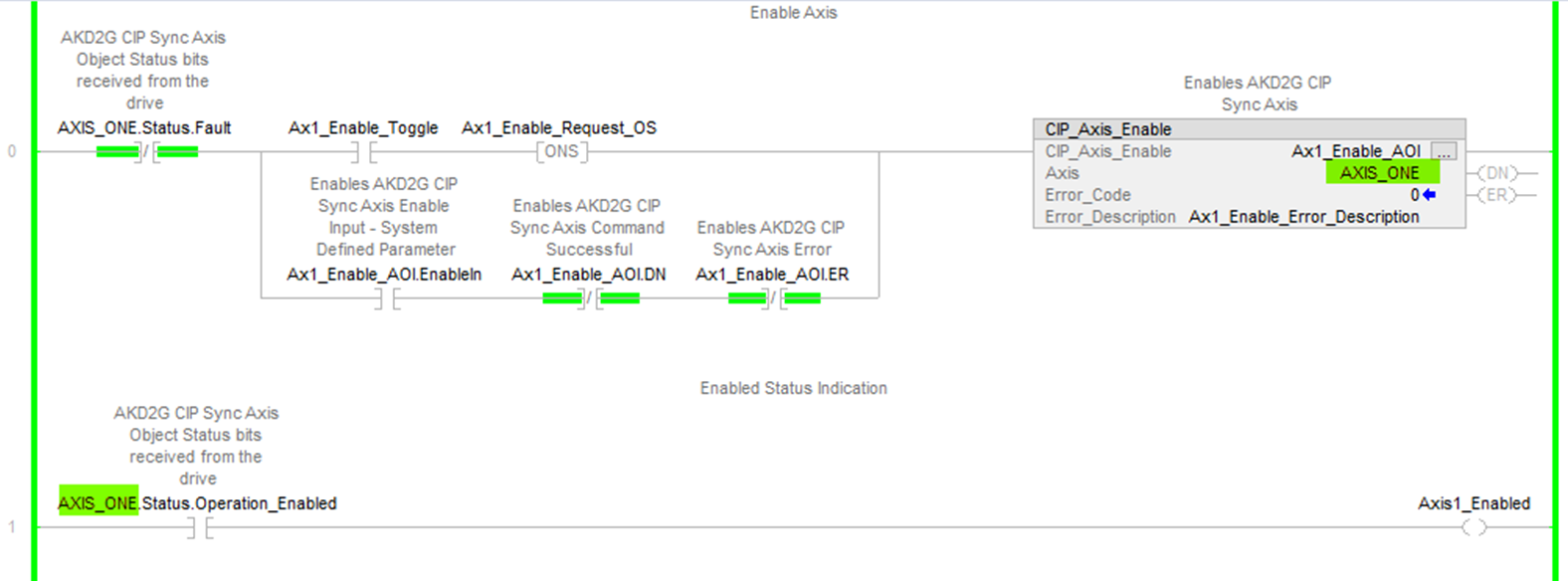
- The CIP_Axis_Enable AOI on execution sends a requested action that the CIP_Axis_State_Machine receives.
- The CIP_Axis_State_Machine serves the request by setting the correct control bits in the Axis_Internal variable.
- The CIP_Drive_Comms AOI copies the Axis_Internal data and sends it out over Ethernet/IP as the Output via the AKD2G-SPI module.
- The AKD2G-SPI receives the data from the PLC.
- The AKD2G-SPI drive’s response data is sent to the PLC via the AKD2G-SPI module over EtherNet/IP.
- The CIP_Drive_Comms copies the response data into the Axis_Internal variable.
- The Axis_Internal data is used by the CIP_Axis_Enable AOI (which monitors the status data for acknowledgment).
Operands
These entries are required by the user.
|
Operand |
Data Type |
Format |
Description |
|---|---|---|---|
|
CIP_Drive_Comms |
CIP_Drive_Comms |
Tag |
Tag name for this instance of the AOI. |
|
InputFromDrive |
_01C4:002B_0014_6C20DCAD:I:0 |
Tag |
|
|
OutputToDrive |
_01C4:002B_0014_4DBB4234:O:0 |
Tag |
|
|
Axis1 |
CIP_Axis |
Tag |
|
|
Axis2 |
CIP_Axis |
Tag |
|
|
VirtualAxis1 |
AXIS_VIRTUAL |
Tag |
|
|
VirtualAxis2 |
AXIS_VIRTUAL |
Tag |
|
|
MotionGroup |
MOTION_GROUP |
|
User tag defining the name of the MotionGroup controlling the given AKD2G drive. |
|
DynamicMap |
CIP_DynamicMap |
Tag |
User tag which creates a structure and arrays where input data is SINT[40] and output data is SINT[32] (which correspond to bytes). |
Structure
These fields are not entered by the user and are populated automatically with Read Only data once the Operands (in the Operand table for this AOI) are entered or presented as output data (bits).
|
Mnemonic |
Data Type |
Description |
|---|---|---|
|
.EnableIn |
BOOL |
The Enable Input bit indicates the instruction is enabled. |
|
.EnableOut |
BOOL |
The Enable Output bit is the output of the Enable Input (.EnableIn) bit. |
Execution
|
Condition |
Ladder Diagram Action |
|---|---|
|
Prescan |
Clear the entire Command Assembly Data Structure. |
- Copy the input data from the AKD2G Module entered in the
- Axis1 and Axis2 have the tag names in the
- Axis1 and Axis2 have the tag names in the
- Copy the input data from the AKD2G Module entered in the
- Where DynamicMap is an internal alias for the DynamicMap tag name field entry of the
- In the Sample project the name is DynamicMap is used.
- Where DynamicMap is an internal alias for the DynamicMap tag name field entry of the
- Move the Axis1.Input and Axis2.Input data (response assembly) to the Axis1.Status and Axis2.Status bits of the structures. (i.e., AXIS_ONE.Status, AXIS_TWO.Status).
- Copy the Axis1.Input.Data and Axis2.Input.Data representing Position Command reported in the response assembly into Axis1.PositionCommand and Axis2.PositionCommand respectively.
- Where Axis1 and Axis2 are declared as AXIS_ONE and AXIS_TWO in the Sample project.
- Copy the Axis1.Input.Data and Axis2.Input.Data representing Position Feedback (actual) reported in the response assembly into Axis1.PositionFeedback and Axis2.PositionFeedback respectively.
- Where Axis1 and Axis2 are declared as AXIS_ONE and AXIS_TWO in the Sample project.
- Copy the internal data from AXIS_ONE.Control and AXIS_TWO.Control bits to the Axis1.Output and Axis2.Output data.
- Use the GSV instruction to read the Motion Group Cycle Start Time.
- This represents the timer event that starts the update cycle.
- Copy the time value into the Axis1.Output and Axis2.Output for the System Timestamp.
- The destination is ultimately the System Timestamp bytes (Axis 1 bytes 6-13; Axis 2 bytes 20-27) of the CIP Sync Command Assembly Data Structure (105).
- Move the VirtualAxis1 Command Position into the temp variable, AxisPosition.
- Copy from the AxisPosition into Axis1.Output data for the Position Command to the axis in the drive.
- The destination is ultimately the Position Command bytes for Axis 1 of the CIP Sync Command Assembly (Axis 1 bytes 2-5).
- Move the VirtualAxis2 Command Position into the temp variable, AxisPosition.
- Copy from AxisPosition into the Axis2.Output data for the Position Command to the axis in the drive.
- The destination is ultimately the Position Command bytes for Axis 2 of the CIP Sync Command Assembly (Axis 2 bytes 16-19) .
- Copy the Axis1.Output and Axis2.Output data (14 bytes each) to the fixed region of the command assembly.
- This was sent to the AKD2G module via the OutputToDrive field entry of the
- This was sent to the AKD2G module via the OutputToDrive field entry of the
- Copy the data of the DynamicMap.Output (32 bytes) to the dynamic map region of the command assembly.
- This was sent to the AKD2G module via the OutputToDrive field entry of the
- This was sent to the AKD2G module via the OutputToDrive field entry of the
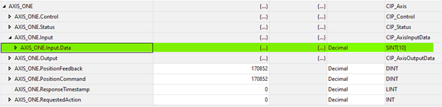
Figure 2: Axis 1 declared as AXIS_ONE
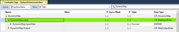
Figure 3: DynamicMap.Input in the structure
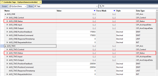
Figure 4: Location of AXIS_ONE.Status and AXIS_TWO.Status
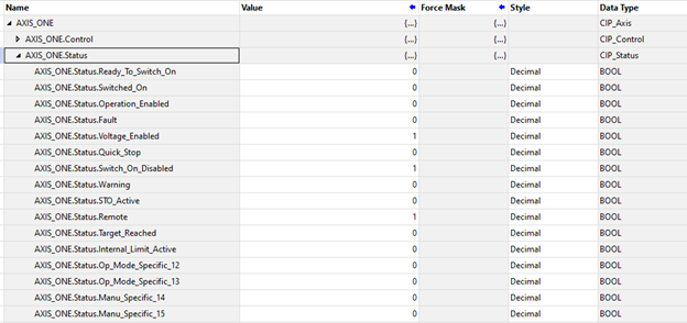
Figure 5: Structure of AXIS_ONE.Status
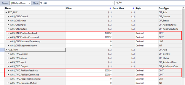
Figure 6: AXIS_ONE and AXIS_TWO
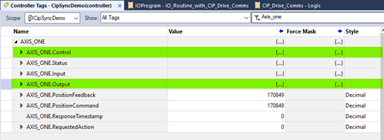
Figure 7: AXIS_ONE.Control and AXIS_ONE.Output
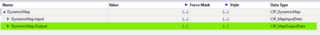
Figure 8: DynamicMap.Output
Changes to Axis Status Bits
- All status bits are updated from the drive.
- See the Status Word in CIP Sync Response Assembly Data Structure (106).
- See CIP Sync: State Machine.
Example of Usage/Programming Guidelines
Figure 9, taken from the Sample project, demonstrates usage.
- The
- This is executed by the IOTask configured to trigger and execute on the Motion Group Execution trigger with a Priority of 1.
- The
- The virtual axes in the Motion Group the AKD2G-SPI axes are correlated to by the
- The axis names using the Studio 5000 Motion Instructions Axis field.
- The virtual axes in the Motion Group the AKD2G-SPI axes are correlated to by the
- The Studio 5000 IOT (Immediate Output) immediately updates the output data (of the given AKD2G Module) necessary for CIP Sync timing.
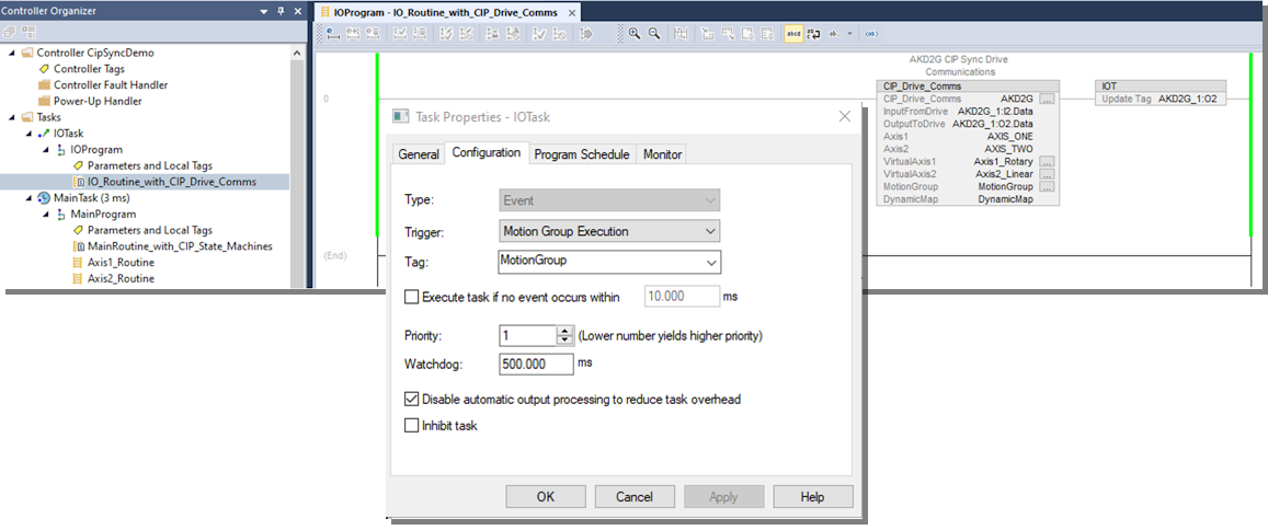
Figure 10 shows the field entries of the

Notes
- Tag names in the instructions associated with the AKD2G Module are under Ethernet in the Controller Organizer.
- Axis tag names used in the Kollmorgen supplemental AOIs for the Axis name.
- The names of the Virtual Axes and corresponding MotionGroup tag names are used in the Studio 5000 Motion Instructions Axis' name.
- The
- They are used in the Kollmorgen-provided supplementary CIP Axis AOIs’ Axis field.
Troubleshooting
None
Step Summary
None
Revision History
|
Revision Number |
Description/Notes |
Date of Revision |
|---|---|---|
|
v1.5 |
Initial release named CIP_Drive_Comms. |
March 2024 |
|
v2.0 |
Renamed CIP_Drive_Comms_Dual_Axis. |
March 2025 |
|
v2.1 |
|
June 2025 |