This section covers how to set each feed forward.
Torque Feed Forwards
-
Acceleration Feed forward: Compensates for mass of the load, higher load = higher acceleration feed forward
-
Velocity Feed forward: Compensates for viscous friction
-
Friction Feed forward: Compensates for static friction
Determining the Acceleration and Velocity Feed Forwards
To tune the Acceleration and Velocity Feed Forwards, complete the following:
-
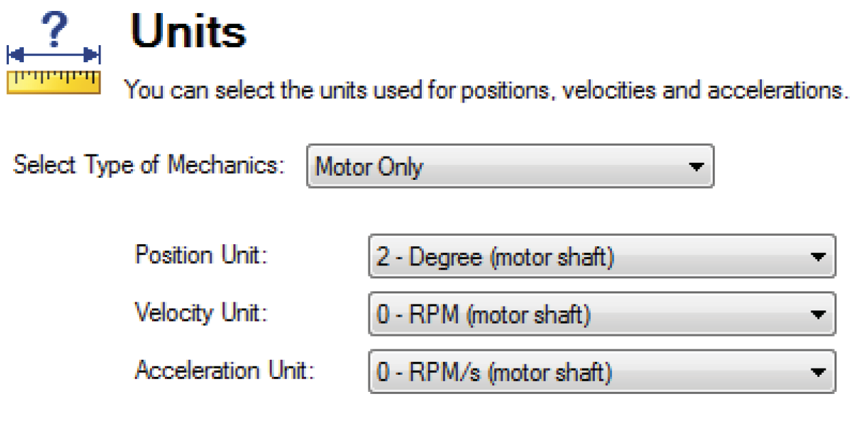
Set the drive units.

-
Set up Motion Tasks 0 and 1 as shown. Use a 50 ms dwell delay between motion tasks

-
Home the axis.

-
Set Velocity feed forward to unity (pass through) and the integral gains and acceleration feed forward to zero.
Save the integral gain values before setting them to zero so they can be set back after tuning the feed forwards.
Note: Integral gains must be set to zero for visual feed forward tuning. Integral gains distort the shapes

-
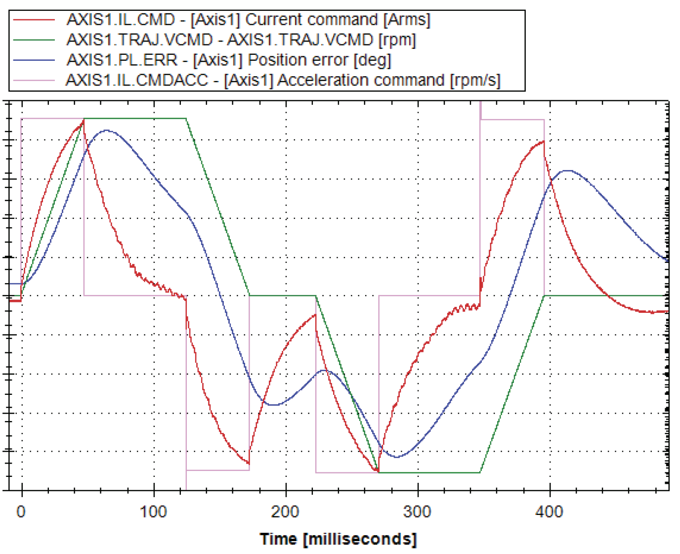
Set Scope channels.
Note:
-
Channels shown are for AKD2. For AKD1 simply remove AXIS#.
-
TRAJ.VCMD does not exist for AKD1, instead use MT.VCMD for AKD1

-
-
Set up the recorder.
Note: TRAJ.VCMD does not exist for AKD1 instead use MT.VCMD for AKD1.

-
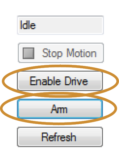
Enable the motor, then Arm the recorder.

-
Start Motion to trigger scope recording.

-
Verify feed forwards are cleared:
-
AXIS1.IL.FRICTION = 0 (Friction)
-
AXIS1.IL.KACCFF = 0 (Acceleration)
-
AXIS1.IL.KVFF = 0 (Current)
-
AXIS1.VL.KVFF = 1 (Velocity)
-
Note: To return to a default state, reset all three of these keywords.
-
Tuning Feed Forwards
Follow these steps to tune your feed forwards:
Identify which trajectory component contributes the most error. In this example, every time the axis accelerates, the error increases in the same direction, so begin with IL.KACCFF.
Record the PL.ERR min/max before changing any tuning parameter so you can measured any improvement (or regression).
Start changing gains slowly, too much feed forward can be worse than too little.
Change IL.KACCFF from 0 to a small value, here we use 0.1.
Visually the plot of PL.ERR does not change much, but if comparing Peak-Peak indicates we reduced Peak-Peak error from 86 to 79 degrees. This is approximately 10% reduction. Using this information we should try ~10x the gain.
Changing IL.KACCFF to 1.0 (10x our previous gain), we see significant improvement, now the error profile no longer follows the acceleration of the trajectory.


Since the shape now appears to follow the Trajectory Velocity, so IL.KVFF should be the next gain. Follow the same strategy.
Repeat process as needed until performance requirements are met.
Referenced Parameters
| Parameter | Description | Drive Keyword |
|---|---|---|
|
IL.CMD |
Current Loop Current Command |
|
|
IL.CMDACC |
Current Loop Command Acceleration |
|
|
IL.FRICTION |
Current Loop Friction Feed Forward |
|
|
IL.KACCFF |
Current Loop Acceleration Feed Forward |
|
|
PL.ERR |
Position Loop Error |
|
|
PL.KI |
Positioon Loop Integral Gain |
|
|
PL.KP |
Position Loop Proportional Gain |
|
|
TRAJ.VCMD |
Trajectory Command |
|
|
VL.CMD |
Velocity Command |
|
|
VL.FB |
Velocity Feedback |
|
|
VL.KI |
Velocity Loop Integral Gain |
|
|
VL.KP |
Velocity Loop Proportional Gain |
|
|
VL.KVFF |
Velocity Loop Feed Forward |


