VL.KP - Velocity Loop Proportional Gain6
| Parameter | Description | Drive Keyword |
|---|---|---|
|
PL.KP |
Position Loop Proportional Gain |
|
|
VL.KI |
Velocity Loop Integral Gain |
|
|
VL.KP |
Velocity Loop Proportional Gain |
Review: The Controller [C] trace shows the frequency response of VL.KP, VL.KI, PL.KP, AR Filters 1 & 2
Lets see how VL.KP affects the response of the Controller plot:
VL.KP = 0.010 Amps / rad/s
(Note: All other tuning is zero)
Converting to Log = 20 * log (0.010)
= -40 dB
Which is what we see in the Plot

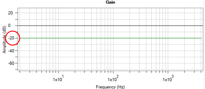
Lets increase VL.KP x 10 to 0.100
VL.KP = 0.100 Amps / rad/s
(Note: All other tuning is zero)
Converting to Log = 20 * log (0.100)
= -20 dB
Which is what we see in the Plot

An important fact to remember when tuning VL.KP is that it is one of the only ways to increase (or decrease) system gain without modifying the Phase of the system.
All values of VL.KP keep the Phase of the Controller at 0 degrees.
Here, VL.KP is set to 1.0 yielding a system gain of 0dB.
Notice the phase stays at 0 degrees.

This same calculation can be used to determine how much VL.KP you need to give the system X dB of gain.
Problem: A resonance is present that needs to be attenuated by 6 dB, and done so by lowering the overall gain of your system.
The current value of VL.KP in your system is 0.630 Amps / rad/s.
What value of VL.KP will lower your gains by 6dB?
Solution: Start by calculating the system gain you currently have.
Gain = 20 * log (0.630) = ~ -4.01 dB
Solve for desired gain = -4.01 dB – 6 dB = 20 * log (VL.KP)
VL.KP = 10^(-10.01dB / 20) = 0.316 Amps / rad/s
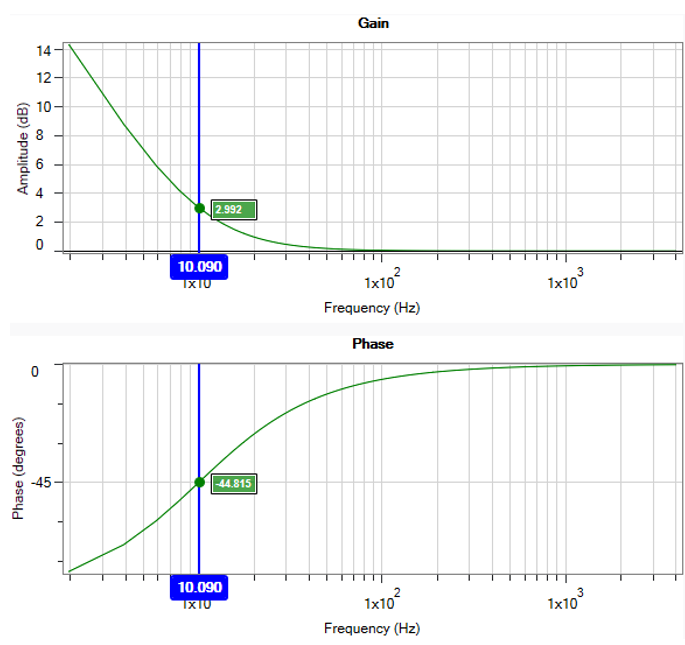
It is worthwhile to mention, that VL.KI (integral gain) ALWAYS reduces the phase in a system. When phase is reduced in a system, that is equivalent with saying the Stability has been reduced. Care should be taken when tuning VL.KI. Too much integral gain will cause low frequency oscillations that often grow out of control into a runaway situation.


