Set Unit Scaling and Modulo
Prior to downloading, the Virtual Axis and Kollmorgen Essentials EtherNet/IP and WorkBench Unit Scaling and Modulo must be set.
Axis 1 Rotary Virtual Axis and Kollmorgen Essentials EtherNet/IP and WorkBench Unit Scaling
-
- On the Kollmorgen Essentials axis, Modulo is only necessary when using a Rotary axis.
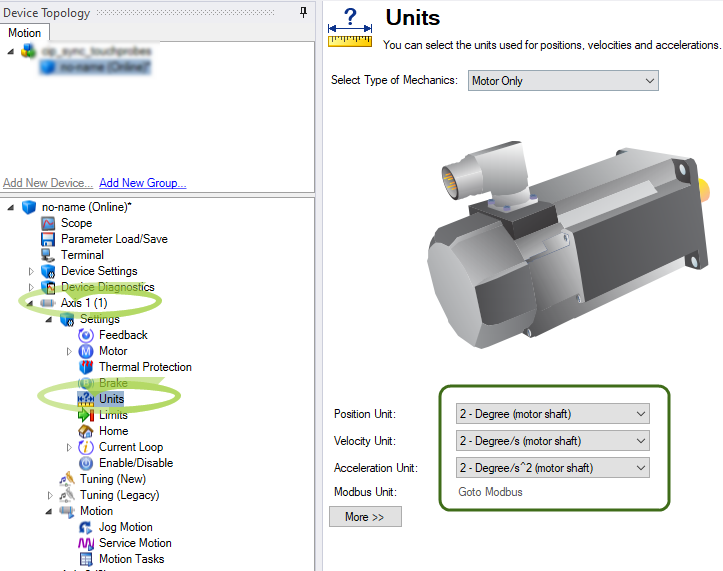
Set WorkBench Units
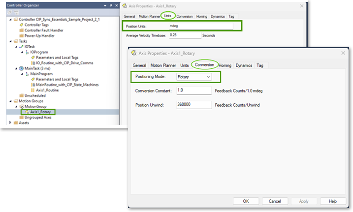
In the Studio 5000 Sample project, Axis 1 is configured as a Virtual Axis in the MotionGroup under the name Axis1_Rotary.
The Units are in millidegrees with a:
- Conversion Constant of 1.0 (where 360000 = 360 degrees).
- Position Unwind of 360000.
This is correlated in the Axis 1 Units and EtherNet/IP Scaling in WorkBench.
The Sample project and drive setup assumes Axis 1 is a direct drive rotary where the application units are in degrees.
Setting EtherNet/IP Units Scaling
For WorkBench Units to align with EtherNet/IP units (and the Virtual Axis) it is necessary to scale the ratio input and ratio output for position, velocity, and acceleration units.
In WorkBench, navigate to Device Settings > Communications > EtherNet/IP > Axis 1 > Scaling tab.
The scaling is:
- Ratio Input: 360000 (EIP counts).
- Ratio Output: 1 (motor rev).
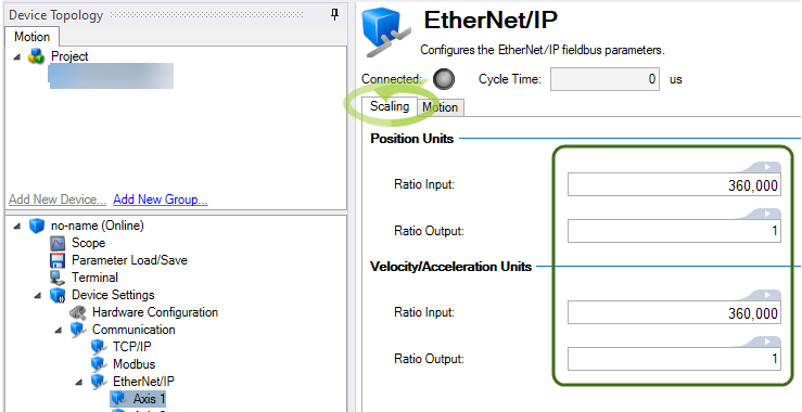
This facilitates scaling for the Real Axis in the drive to follow the Virtual Axis’ trajectory when a Motion Instruction (i.e., MAJ) is used.
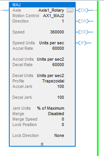
Example:
- Speed is set to 360000 or 360 deg/s.
- Accel/Decel are set to 60000 or 60 deg/s^2.
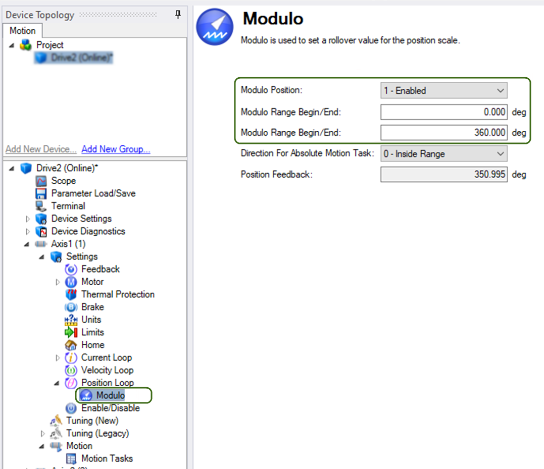
Setting Modulo
-
- On the Kollmorgen Essentials axis, Modulo is only necessary when using a Rotary axis.
Since Axis 1 is setup as Rotary and the Virtual Axis has a Position Unwind of 360000 (mdeg), it is very important to:
- Enable the Modulo.
- Set the range in the AKD2G-SPI for Axis 1 so the axis never exceeds the range of the Position Unwind of the Virtual Axis.
Axis 2 Linear Virtual Axis and AKD2G EtherNet/IP and WorkBench Unit Scaling
-
- Example of Essentials Linear Axis Setup
The Sample Project demonstrates a Rotary Type Virtual Axis and Kollmorgen Essentials Drive setup. This procedure is used to change the setup for Axis 1 to be Linear.
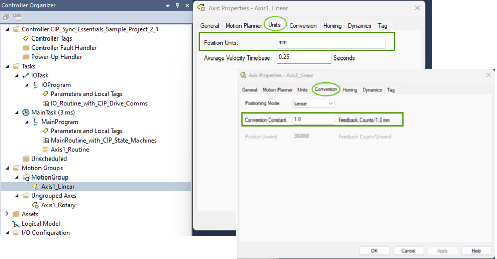
A virtual axis must be created in the Motion Group in Studio 5000 named (i.e.Axis2_Linear) to demonstrate the case of a linear axis in the application.
Units are assumed to be millimeters and a conversion constant of 1.0 Feedback Counts/1.0 mm. Since the Virtual Axis is declared with a Linear Positioning Mode the Position Unwind is grayed out, making it unnecessary to enable Modulo in Axis 2 of the AKD2G-SPI.
In the Sample project, a second Virtual Axis named Axis2_Linear, was created in the MotionGroup in order to demonstrate the case of a linear axis in the application.
Units are assumed to be millimeters and a Conversion Constant of 1.
*These settings are for demonstration and are application dependent.
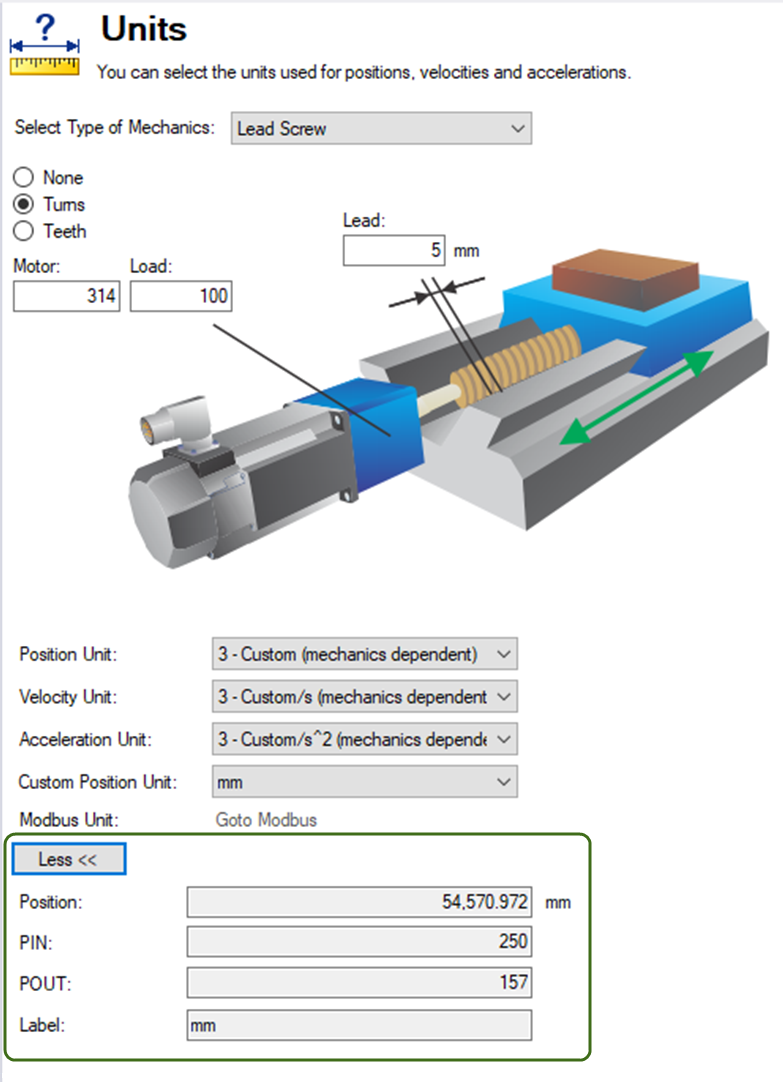
This example uses the following mechanics:
-
5 mm ballscrew with a 3.14 to 1 gear reducer
-
WorkBench Units were set normally to model the mechanics
-
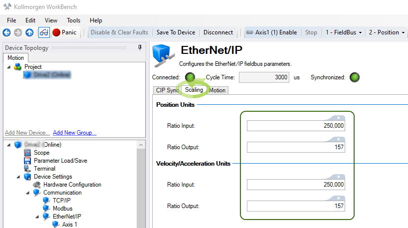
Click the More button to view the calculated PIN and POUT for WorkBench Units (i.e., PIN = 250 and POUT = 157).
Note the Ratio Input and Ratio Output under the Scaling view (Communication > EtherNet/IP > Axis
- Ratio Input: 250 x 1000 (to handle the integer to floating point scaling).
- Ratio Output: 157.
This facilitates scaling for the Real Axis in the drive to follow the Virtual Axis’ trajectory when a Motion Instruction (i.e., MAJ) is used.
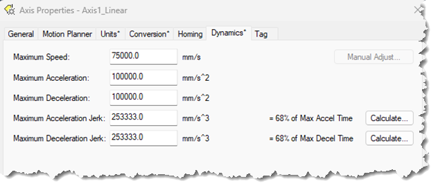
Example:
- Speed is set to 10000 (equivalent to 10 mm/s).
- Accel/Decel are set to 60000 (equivalent to 60 mm/s^2).
Since modulo isn’t used on a Linear axis when converting from the Sample Project and procedure for Axis1_Rotary navigate to the Modulo screen under Axis1->Position Loop->Modulo and select Disable.
Note the Sample Project must be edited to point to the Axis1_Linear instead of the old Axis1_Rotary to convert to linear.
-
CIP_Drive_Comms_Single_Axis AOI->Virtual Axis field.
-
CIP_Axis_State_Machine AOI->Virtual Axis field.
Note the Rockwell instructions demonstrated in the Sample Project must all be edited to point to the Axis1_Linear virtual axis and any values/scaling to change from units degrees, degrees/s, degree/s^2.
MAJ instructions for Jog Forward and Reverse:
Note the AKD2G Axis 2 example in the AKD2G CIP Sync Sample Project can be used as a guideline for values:
MAM Instructions for Extend and Retract moves:
Note the AKD2G Axis 2 example in the AKD2G CIP Sync Sample Project can be used as a guideline for values:
MAS instruction:
MOV instructions for displaying Command and Actual (feedback) Positions in the ladder: