Define the PLC Cycle
The cycle specification defines the number of cycles between successive executions of the programs.
Procedure
- In the Project Explorer, expand the PLC node.
- Right-click on Programs and select Cycle. (Figure 1)
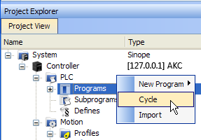
Figure 1: PLC > Programs > Cycle
The Cycle dialog box opens. (Figure 2)
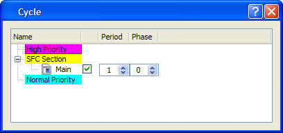
The Cycle dialog box is used to:
- Change the Period and Phase parameters.
- Configure the programs priority into the Virtual Machine.
|
Column |
Description |
|---|---|
|
Name |
List of PLC programs grouped together by priority level.
|
|
Check box |
Enables or disables the execution of the corresponding program. |
|
Period |
Defines how many cycles are set between two executions of the program.
|
|
Phase |
Defines an offset that enables you to dispatch slow programs among few cycles. The goal of postponing the program execution is to reduce execution peak loads. Examples
|
In the High and Normal Priority sections, adjust the order of the programs with a drag-and-drop operation according to the expected sequence. In each section, the program on the top is executed first.
Select the program to set with a higher priority, then drag and drop it to the relevant priority level. (Figure 3)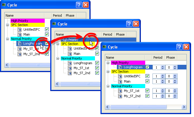
Figure 3: Change Priorities by Defining the Cycle
If all programs are with a Period set to 1, the KAS-IDE is more loaded. The choice of the Period for the programs gives you the possibility to distribute the load of the application.
See Also
Specify the Duration of a Cycle
This parameter is defined in EtherCAT Master Settings tab.
Ensure Variables are Exported
Program Organization Units (POUs) containing variables (see Map Variables to HMI) must be compiled for the variable to be exported.
Example
In the Figure 7 images, a POU (UntitledST) has two variables: NewVar and NewVar1.
- Only NewVar1 is set to be exported (Figure 4).
- The POU, however, is not set to be executed in the Cycle dialog box (Figure 5).
- This causes a compile error (Figure 6).
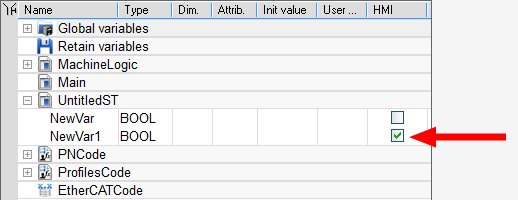
Figure 4: NewVar1 is set to be exported
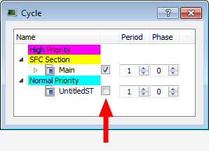
Figure 5: POU is not set to be executed
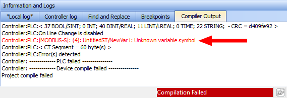
Figure 7: Examples of a variable not being exported and the resulting compile error.