Enable/Disable
Each axis can be independently enabled or disabled using both hardware and software methods.

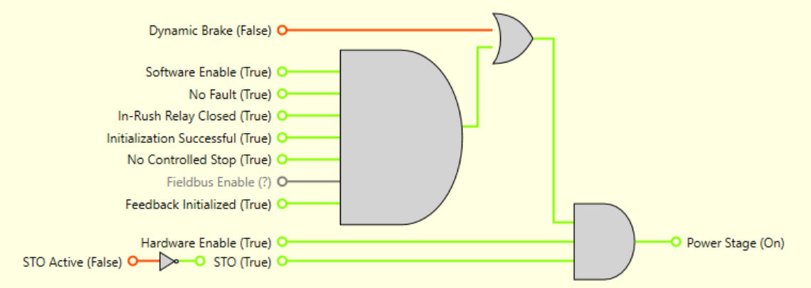
Hardware Enable
AXIS#.HWEN.SOURCE selects the digital input, DIN, used as the hardware enable input. If this input is high the drive can be enabled. By default, DIN 3 is used as the input for axis 1 and DIN 4 is used as the input for axis 2. Selecting 0 will not use any digital input as a as a hardware enable. AXIS#.HWEN.STATE allows you to see the state of the hardware enable.
AXIS#.HWEN.MODE is used to select whether faults are cleared on the rising edge of the hardware enable input. Selecting 0 will issue AXIS#.CLRFAULTS on the rising edge of the hardware enable input and selecting 1 will not attempt to clear any faults, allowing for review of any that have occurred.
If you want both axes, use the same input to enable both axes then set AXIS#.HWEN.SOURCE on both axes to the same input.
You can use the corresponding DIN#.FILTER to modify the filtering of the input and DIN#.INV to change the polarity of the hardware enable.
Software Enable
AXIS#.EN enables the axis and AXIS#.DIS disables the axis.
AXIS#.ENDEFAULT allows you to select what state the software enable is when the drive powers up.
Bit 0 of AXIS#.DISSOURCES allows you to see the current state of the software enable. Other bits indicate the reason an axis is disabled.
Disable Modes
AXIS#.DISMODE allows you to select what happens when the axis disables. This setting applies to the axis if it is disabled by the hardware or the software enable.
Mode 0: Immediately disable axis.
The axis will immediately disable the power stage and the motor will coast to a stop, or in the case of a vertical or overhung load, will fall abruptly. If a brake is present, the brake will be applied according to AXIS#.MOTOR.BRAKEIMM and "AXIS#.MOTOR.TBRAKEAPP ".
Mode 1: Dynamic Brake to a stop.
The axis uses the Dynamic Braking to stop the motion and then the power stage will be disabled. In most cases, the driven motor stops quickly (pending the joules available and load circumstances). In the case of an overhung or vertical load, the driven motor will attempt to stop, but then continues to allow the load to fall if no measures have been taken to secure the load.
Mode 2: Controlled stop, then disable.
The axis will be brought to a stop using the Controlled Stop values. Once the axis is stationary the axis will then disable.
A controlled stop will decelerate the axis with the AXIS#.CS.DEC deceleration rate to a zero commanded speed. The drive stays enabled until either of the following happens.
a) The measured motor velocity limit is below AXIS#. ZEROV for the AXIS#. ZEROT period.
b) The axis disable times out AXIS#.DISTO is exceeded.
Once one of these conditions is reached, the power stage will be disabled and brake applied (if present).
Mode 3: Controlled stop, then dynamic brake.
Similar to mode 2, the axis decelerates with the AXIS#.CS.DEC deceleration until AXIS#. ZEROV is reached for the AXIS#. ZEROT period. The axis will then hold the axis with the dynamic brake.
The disable timeout AXIS#.DISTO is used in modes 1, 2 and 3. It is the amount of time the axis follows the disable mode before it deactivates the axis regardless of method chosen, and alerts with an Emergency Timeout Fault, F6005 .
All disable modes operate based on the type of disable command received. Any critical faults, hardware disable or STO disable, immediately turn off the power stage, and the motor will coast or free fall depending on how the motor is secured.
For applications that involve a constant force at the load, particularly vertical load applications, minimizing load movement when the power stage disables is a critical concern. See Vertical Loads for direction on setting up this class of applications to operate safely.


