AKT2G-DN-002-000
Up/Down Counter 24 VDC, 100 kHz, 32 bit counter depth
Jump to a section on this page:
The up/down counter counts binary pulses, and transmits the counter state, in an electrically isolated form, to the higher-level automation device.
The AKT2G-DN-002 EtherCAT Terminal can alternatively be operated as:
- a single-channel counter (32 bit) that can be toggled between counting up and down via the U/D input (delivery state)
- a single-channel counter (32 bit) that is controlled via the gate connection
- two separate logic counters (32 bit) that can count in one direction only with the Clock 1 and Clock 2 inputs
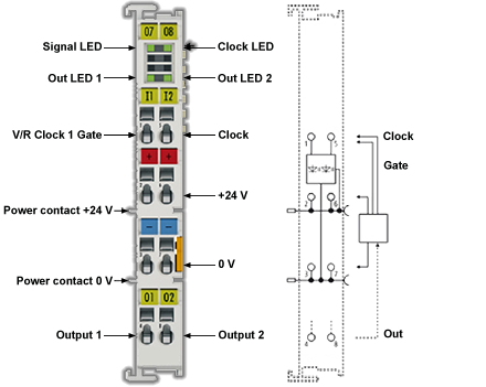
The signal state of the inputs and outputs is indicated by light emitting diodes.
The two outputs (Output 1 and Output 2) are switched in relation to the counter value and can thus be used as fast control signals for field devices.
The AKT2G-DN-002 supports distributed clocks, i.e., the input data can be monitored synchronously with other data that are also linked to distributed clock terminals. The accuracy across the system is < 100 ns.
Related Topics: Map Input and Output to Variables
LEDs and Connection
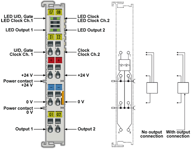
LEDs
| LED | Color | Meaning |
|---|---|---|
|
UP/DOWN, GATE CLOCK CH.1 |
green |
Signal at U/D, Gate input (operating mode 32 bit up/down counter, 32 bit gated counter) Signal at the Clock input, channel 1 (operating mode 2 x 32 bit counter) |
|
CLOCK CLOCK CH.2 |
green |
Signal at Clock input (operating mode 32 bit up/down counter, 32 bit gated counter) Signal at the Clock input, channel 2 (operating mode 2 x 32 bit counter |
|
OUTPUT1 OUTPUT2 |
green |
Signal at the corresponding output |
Connection
| Terminal Point | Description | |
|---|---|---|
| Name | No. | |
|
U/D, Gate Clock Ch.1 |
1 |
Up/down input (operating mode 32 bit up/down counter), Gate input (operating mode 32 bit counter with gate function) Clock 1 input (operating mode 2 x 32 bit counter) |
|
+24 V |
2 |
+24 V (internally connected to terminal point 6 and positive power contact) |
|
0 V |
3 |
0 V (internally connected to terminal point 7 and negative power contact) |
|
Output 1 |
4 |
Output 1 |
|
Clock Clock Ch.2 |
5 |
Clock input (operating mode 32 bit up/down counter) and (operating mode 32 bit counter with gate function) Clock 2 input (operating mode 2 x 32 bit counter) |
|
+24 V |
6 |
+24 V (internally connected to terminal point 2 and positive power contact) |
|
0 V |
7 |
0 V (internally connected to terminal point 3 and negative power contact) |
| Output 2 | 8 | Output 2 |
Basic Function Principles
The AKT2G-DN-002 input terminals count binary pulses and transfer the current value to the higher-level controller.
In addition to the 32 bit up/down counter, further available operating modes are a 32 bit gated counter or two 32 bit counters. In gated counter mode, a low or high level at the Gate input inhibits the counting function of the terminal.
If two 32 bit counters are active, the U/D input (terminal point 1) is configured as the input for the first counter and the Clock 2 input (terminal point 5) as the input for the second counter.
Beyond that, two digital outputs can be set.
The maximum input frequency is limited to 100 kHz for the AKT2G-DN-002; the counters react to the rising edge of the input signal.
Operating Mode Selection
The following operation modes are possible.
| Operation mode | Predefined PDO Assignment | Setting of the counting direction via CoE directory | Switchable outputs |
|---|---|---|---|
|
1 (default) |
1Ch. +/- Counter: 0x1A02 – CNT Inputs + 0x1602 – CNT Outputs |
Index 0x8020:05: 0: Enable UD counter
|
Output 1 |
|
2 |
1Ch. +/- Counter: 0x1A02 – CNT Inputs + 0x1602 – CNT Outputs |
Index 0x8020:05: 1: Enable pos. gate
indicates the individual pulses. + Index 0x8020:04: 0: up counter 1: down counter |
Output 1 |
|
3 |
1Ch. +/- Counter: 0x1A02 – CNT Inputs + 0x1602 – CNT Outputs |
Index 0x8020:05: 2: Enable neg. gate
+ Index 0x8020:04: 0: up counter 1: down counter |
Output 1 |
|
4 |
2Ch. Counter: 0x1A00 – CNT Inputs Channel 1 0x1A01 – CNT Inputs Channel 2 + 0x1600 – CNT Outputs Channel 1 0x1601 – CNT Outputs Channel 2 |
Index 0x8000:04 (Channel1) and 0:up counter 1:down counter |
Counter 1 → Output 1 Counter 2 → Output 2 |
In addition, the distributed clock function may be activated for the AKT2G-DN-002.
Single-channel up/down counter, gated counter (operating mode 1-3)
- Selection of the PDOs for "1Ch.+/-Counter"
- CoE Init-command to configure index 0x8020:05:
- "Enable UD counter" – single-channel up/down counter (operating mode 1)
If a high signal level is encountered at the up/down input of the terminal (terminal point 1), the counter counts up in the event of positive edges at the clock input (terminal point 5), with a low signal level it counts down. - "Enable pos. gate" – single-channel gated counter closes in the case of a high level (operating mode 2)
The counter is inhibited if a high level is encountered at the gate input of the terminal (terminal point 1).
The counting direction is set by index 0x8020:04 (0: up, 1: down). The clock input (terminal point 5) indicates the individual pulses. - "Enable neg. gate" – single-channel gated counter closes in the case of a low level (operating mode 3)
The counter is inhibited if a low level is encountered at the gate input of the terminal (terminal point 1).The counting direction is set by index 0x8020:04 (0: up, 1: down).
The clock input (terminal point 5) indicates the individual pulses.
- "Enable UD counter" – single-channel up/down counter (operating mode 1)
Two-channel up/down counter (operating mode 4)
- Selection of the PDOs for "2Ch. Counter"
The terminal points 1 or 5 serve as clock input for 32 bit counter 1 or 2. - CoE Init-commands to configure the indices 0x8000:04 for channel 1 and 0x8010:04 for channel. Two options are available per channel:
- 0: up counter
- 1: down counter
Objects for Commissioning
| Index (hex) | Name | Meaning | Data type | Flags | Default |
|---|---|---|---|---|---|
|
1011:0 |
Restore default parameters |
Restore default parameters |
UINT8 |
RO |
0x01 (1dec) |
|
1011:01 |
SubIndex 001 |
If this object is set to “0x64616F6C” in the set value dialog, all backup objects are reset to their delivery state. |
UINT32 |
RW |
0x00000000 (0dec) |
| Index (hex) | Name | Meaning | Data type | Flags | Default |
|---|---|---|---|---|---|
|
8000:0 |
CNT Settings Ch.1 |
Maximum subindex |
UINT8 |
RO |
0x13 (19dec) |
|
8000:01 |
Enable function to set output |
Activates the function for setting Output 1 |
BOOLEAN |
RW |
0x00 (0dec) |
|
8000:02 |
Enable function to reset output |
Activates the function for resetting Output 1 |
BOOLEAN |
RW |
0x00 (0dec) |
|
8000:03 |
Enable reload |
The counter counts to the value in index 0x8000:13 |
BOOLEAN |
RW |
0x00 (0dec) |
|
8000:04 |
Count down |
Counting direction: • 0: Up • 1: Down |
BOOLEAN |
RW |
0x00 (0dec) |
|
8000:11 |
Switch on threshold value |
Switch-on threshold value for Output 1 |
UINT32 |
RW |
0x00000000 (0dec) |
|
8000:12 |
Switch off threshold value |
Switch-off threshold value for Output 1 |
UINT32 |
RW |
0x00000000 (0dec) |
|
8000:13 |
Counter reload value |
The limit that can be activated via "Enable reload" (index 0x8000:03). The counter counts to this limit and, on exceeding it, begins again at zero. |
UINT32 |
RW |
0x00000001 (1dec) |
| Index (hex) | Name | Meaning | Data type | Flags | Default |
|---|---|---|---|---|---|
|
8010:0 |
CNT Settings Ch.2 |
Maximum subindex |
UINT8 |
RO |
0x13 (19dec) |
|
8010:01 |
Enable function to set output |
Activates the function for setting Output 2 |
BOOLEAN |
RW |
0x00 (0dec) |
|
8010:02 |
Enable function to reset output |
Activates the function for resetting Output 2 |
BOOLEAN |
RW |
0x00 (0dec) |
|
8010:03 |
Enable reload |
The counter counts to the value in index 0x8010:13 |
BOOLEAN |
RW |
0x00 (0dec) |
|
8010:04 |
Count down |
Counting direction • 0: Up • 1: Down |
BOOLEAN |
RW |
0x00 (0dec) |
|
8010:11 |
Switch on threshold value |
Switch-on threshold value for Output 2 |
UINT32 |
RW |
0x00000000 (0dec) |
|
8010:12 |
Switch off threshold value |
Switch-off threshold value for Output 2 |
UINT32 |
RW |
0x00000000 (0dec) |
|
8010:13 |
Counter reload value |
The limit that can be activated via "Enable reload" (index 0x8010:03). The counter counts to this limit and, on exceeding it, begins again at zero. |
UINT32 |
RW |
0x00000001 (1dec) |
| Index (hex) | Name | Meaning | Data type | Flags | Default |
|---|---|---|---|---|---|
|
8020:0 |
CNT Settings |
Maximum subindex |
UINT8 |
RO |
0x13 (19dec) |
|
8020:01 |
Enable function to set output |
Activates the function for setting Output 1 |
BOOLEAN |
RW |
0x00 (0dec) |
|
8020:02 |
Enable function to reset output |
Activates the function for resetting Output 1 |
BOOLEAN |
RW |
0x00 (0dec) |
|
8020:03 |
Enable reload |
The counter counts to the value in index 0x8020:13 |
BOOLEAN |
RW |
0x00 (0dec) |
|
8020:04 |
Count down |
Counting direction • 0: Up • 1: Down |
BOOLEAN |
RW |
0x00 (0dec) |
|
8020:05 |
Operating mode |
Operating mode • 0: Enable UD counter U/D input (terminal point 1) specifies the counting direction: High level: up, low level: down • 1: Enable pos. gate (gate inhibits with positive level) • 2: Enable neg. gate (gate inhibits with negative level) |
BIT2 |
RW |
0x00 (0dec) |
|
8020:11 |
Switch on threshold value |
Switch-on threshold value for Output 1 |
UINT32 |
RW |
0x00000000 (0dec) |
|
8020:12 |
Switch off threshold value |
Switch-off threshold value for Output 1 |
UINT32 |
RW |
0x00000000 (0dec) |
|
8020:13 |
Counter reload value |
The limit that can be activated via "Enable reload" (index 0x8020:03 ). The counter counts to this limit and, on exceeding it, begins again at zero. |
UINT32 |
RW |
0x00000001 (1dec) |
Profile-specific objects (0x6000-0xFFFF)
The profile-specific objects have the same meaning for all EtherCAT slaves that support the profile 5001.
| Index (hex) | Name | Meaning | Data type | Flags | Default |
|---|---|---|---|---|---|
|
6000:0 |
CNT Inputs Ch.1 |
Maximum subindex |
UINT8 |
RO |
0x11 (17dec) |
|
6000:01 |
Output functions enabled |
This bit indicates that the internal functions for the output have been enabled |
BOOLEAN |
RO |
0x00 (0dec) |
|
6000:02 |
Status of output |
Status of the output |
BOOLEAN |
RO |
0x00 (0dec) |
|
6000:03 |
Set counter done |
The counter was set |
BOOLEAN |
RO |
0x00 (0dec) |
|
6000:04 |
Counter inhibited |
The counter is stopped for as long as this bit is set |
BOOLEAN |
RO |
0x00 (0dec) |
|
6000:06 |
Status of input clock |
State of the Clock input (high level applied) |
BOOLEAN |
RO |
0x00 (0dec) |
|
6000:0E |
Sync Error |
Synchronization error |
BOOLEAN |
RO |
0x00 (0dec) |
|
6000:10 |
TxPDO Toggle |
The TxPDO toggle is toggled by the slave when the data of the associated TxPDO is updated |
BOOLEAN |
RO |
0x00 (0dec) |
|
6000:11 |
Counter value |
Counter value |
UINT32 |
RO |
0x00000000 (0dec) |
| Index (hex) | Name | Meaning | Data type | Flags | Default |
|---|---|---|---|---|---|
|
6010:0 |
CNT Inputs Ch.2 |
Maximum subindex |
UINT8 |
RO |
0x11 (17dec) |
|
6010:01 |
Output functions enabled |
This bit indicates that the internal functions for the output have been enabled |
BOOLEAN |
RO |
0x00 (0dec) |
|
6010:02 |
Status of output |
Status of the output |
BOOLEAN |
RO |
0x00 (0dec) |
|
6010:03 |
Set counter done |
The counter was set |
BOOLEAN |
RO |
0x00 (0dec) |
|
6010:04 |
Counter inhibited |
The counter is stopped for as long as this bit is set |
BOOLEAN |
RO |
0x00 (0dec) |
|
6010:06 |
Status of input clock |
State of the Clock input (high level applied) |
BOOLEAN |
RO |
0x00 (0dec) |
|
6010:0E |
Sync Error |
Synchronization error |
BOOLEAN |
RO |
0x00 (0dec) |
|
6010:10 |
TxPDO Toggle |
The TxPDO toggle is toggled by the slave when the data of the associated TxPDO is updated |
BOOLEAN |
RO |
0x00 (0dec) |
|
6010:11 |
Counter value |
Counter value |
UINT32 |
RO |
0x00000000 (0dec) |
| Index (hex) | Name | Meaning | Data type | Flags | Default |
|---|---|---|---|---|---|
|
6020:0 |
CNT Inputs |
Maximum subindex |
UINT8 |
RO |
0x11 (17dec) |
|
6020:01 |
Output functions enabled |
This bit indicates that the internal functions for the output have been enabled |
BOOLEAN |
RO |
0x00 (0dec) |
|
6020:02 |
Status of output |
Status of the output |
BOOLEAN |
RO |
0x00 (0dec) |
|
6020:03 |
Set counter done |
The counter was set. |
BOOLEAN |
RO |
0x00 (0dec) |
|
6020:04 |
Counter inhibited |
The counter is stopped for as long as this bit is set |
BOOLEAN |
RO |
0x00 (0dec) |
|
6020:05 |
Status of input UD |
State of the Up/Down input (high level applied) |
BOOLEAN |
RO |
0x00 (0dec) |
|
6020:06 |
Status of input clock |
State of the Clock input (high level applied) |
BOOLEAN |
RO |
0x00 (0dec) |
|
6020:0E |
Sync Error |
Synchronization error |
BOOLEAN |
RO |
0x00 (0dec) |
|
6020:10 |
TxPDO Toggle |
The TxPDO toggle is toggled by the slave when the data of the associated TxPDO is updated |
BOOLEAN |
RO |
0x00 (0dec) |
|
6020:11 |
Counter value |
Counter value |
UINT32 |
RO |
0x00000000 (0dec) |
| Index (hex) | Name | Meaning | Data type | Flags | Default |
|---|---|---|---|---|---|
|
7000:0 |
CNT Outputs Ch.1 |
Maximum subindex |
UINT8 |
RO |
0x11 (17dec) |
|
7000:01 |
Enable output functions |
The internal functions for the output are enabled via this bit |
BOOLEAN |
RO |
0x00 (0dec) |
|
7000:02 |
Set output |
Set output |
BOOLEAN |
RO |
0x00 (0dec) |
|
7000:03 |
Set counter |
Set counter |
BOOLEAN |
RO |
0x00 (0dec) |
|
7000:04 |
Inhibit counter |
The counter is stopped as long as this bit is active. The previous counter state is retained. |
BOOLEAN |
RO |
0x00 (0dec) |
|
7000:11 |
Set counter value |
This is the counter value to be set via “Set counter” (index 0x7000:03). |
UINT32 |
RO |
0x00000000 (0dec) |
| Index (hex) | Name | Meaning | Data type | Flags | Default |
|---|---|---|---|---|---|
|
7010:0 |
CNT Outputs Ch.2 |
Maximum subindex |
UINT8 |
RO |
0x11 (17dec) |
|
7010:01 |
Enable output functions |
The internal functions for the output are enabled via this bit |
BOOLEAN |
RO |
0x00 (0dec) |
|
7010:02 |
Set output |
Set output |
BOOLEAN |
RO |
0x00 (0dec) |
|
7010:03 |
Set counter |
Set counter |
BOOLEAN |
RO |
0x00 (0dec) |
|
7010:04 |
Inhibit counter |
The counter is stopped as long as this bit is active. The previous counter state is retained. |
BOOLEAN |
RO |
0x00 (0dec) |
|
7010:11 |
Set counter value |
This is the counter value to be set via “Set counter” (index 0x7010:03). |
UINT32 |
RO |
0x00000000 (0dec) |
| Index (hex) | Name | Meaning | Data type | Flags | Default |
|---|---|---|---|---|---|
|
7020:0 |
CNT Outputs |
Maximum subindex |
UINT8 |
RO |
0x11 (17dec) |
|
7020:01 |
Enable output functions |
The internal functions for the output are enabled via this bit |
BOOLEAN |
RO |
0x00 (0dec) |
|
7020:02 |
Set output |
Set output |
BOOLEAN |
RO |
0x00 (0dec) |
|
7020:03 |
Set counter |
Set counter |
BOOLEAN |
RO |
0x00 (0dec) |
|
7020:04 |
Inhibit counter |
The counter is stopped as long as this bit is active. The previous counter state is retained. |
BOOLEAN |
RO |
0x00 (0dec) |
|
7020:11 |
Set counter value |
This is the counter value to be set via “Set counter” (index 0x7020:03). |
UINT32 |
RO |
0x00000000 (0dec) |
| Index (hex) | Name | Meaning | Data type | Flags | Default |
|---|---|---|---|---|---|
|
F000:0 |
Modular device profile |
General information for the modular device profile |
UINT8 |
RO |
0x02 (2dec) |
|
F000:01 |
Module index distance |
Index spacing of the objects of the individual channels |
UINT16 |
RO |
0x0010 (16dec) |
|
F000:02 |
Maximum number of modules |
Number of channels |
UINT16 |
RO |
0x0003 (3dec) |
| Index (hex) | Name | Meaning | Data type | Flags | Default |
|---|---|---|---|---|---|
|
F008:0* |
Code word |
NoCoeStorage function: The input code of the code word 0x12345678 activates the NoCoeStorage function: Changes to the CoE directory are not saved if the function is active. The function is deactivated by: 1.) changing the code word or 2.) restarting the terminal. |
UINT32 |
RW |
0x00000000 (0dec) |
* Function NoCoeStorage from Firmware 03
-
-
Code word
The vendor reserves the authority for the basic calibration of the terminals. The code word is therefore at present reserved.
| Index (hex) | Name | Meaning | Data type | Flags | Default |
|---|---|---|---|---|---|
|
F010:0 |
Module list |
Maximum subindex |
UINT8 |
RO |
0x03 (3dec) |
|
F010:01 |
SubIndex 001 |
reserved |
UINT16 |
RO |
0x0096 (150dec) |
|
F010:02 |
SubIndex 002 |
reserved |
UINT16 |
RO |
0x0096 (150dec) |
|
F010:03 |
SubIndex 003 |
reserved |
UINT16 |
RO |
0x0096 (150dec) |
Technical Data
|
Technical Data |
AKT2G-DN-002-000 |
|---|---|
| Number of counters | 1 or 2 |
| Rated voltage | 24 VDC (-15%/+20%) |
| Signal voltage “0” | -3 V ... 5 V (EN 61131-2, type 1) |
| Signal voltage “1” | 15 V ... 30 V (EN 61131-2, type 1) |
| Counting frequency | 100 kHz |
| Counter depth | 32 bit |
| Input current | typ. 5 mA (EN 61131-2, type 1) |
| Output current (per channel) | max. 0.5 A (short-circuit-proof) |
| Distributed Clocks (DC) | yes |
| Current consumption power contacts | typ. 14 mA + load |
| Current consumption via E-bus | typ. 130 mA |
| Electrical isolation | 500 V (E-bus/field voltage) |
| Supports NoCoeStorage function | yes |
| Weight | approx. 50 g |
| Permissible ambient temperature range during operation | -25°C ... +60°C (extended temperature range) |
| Permissible ambient temperature range during storage | -40°C ... +85°C |
| Permissible relative humidity | 95%, no condensation |
| Dimensions (W x H x D) | approx. 15 mm x 100 mm x 70 mm |
| Mounting | on 35 mm mounting rail conforms to EN 60715 |
| Vibration/shock resistance | conforms to EN 60068-2-6 / EN 60068-2-27, see also Mounting and Wiring of I/O Terminals |
| EMC immunity/emission | conforms to EN 61000-6-2 / EN 61000-6-4 |
| Protection class | IP20 |
| Installation position | variable |
| Approval | CE ATEX, cULus |