AKT2G-DT-008-000
8-channel Digital Output Terminal 24 V DC, 0.5 A, 1-wire system
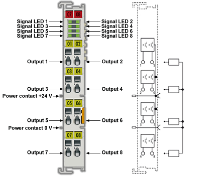
The AKT2G-DT-008 digital output terminal relays binary control signals of the automation device in an electrically isolated manner to the actuators of the process level. They are protected against reverse polarity at the power contacts. The digital output terminals of the device indicate their signal state through an LED for each channel.
Related Topics: Map Input and Output to Variables
AKT2G-DT-008 LEDs and Connection
LEDs
|
LED |
Color |
Meaning |
|
|---|---|---|---|
|
OUTPUT 1- 8 |
green |
off |
No output signal |
|
on |
24 VDC output signal at the respective output |
||
Connection
| Terminal point | Description | |
|---|---|---|
| Name | No. | |
|
Output 1 |
1 |
Output 1 |
|
Output 3 |
2 |
Output 3 |
|
Output 5 |
3 |
Output 5 |
|
Output 7 |
4 |
Output 7 |
|
Output 2 |
5 |
Output 2 |
|
Output 4 |
6 |
Output 4 |
|
Output 6 |
7 |
Output 6 |
|
Output 8 |
8 |
Output 8 |
Technical Data
|
Technical Data |
AKT2G-DT-008-000 |
|---|---|
|
Number of outputs |
8 |
|
Non-reactive outputs |
yes (see Interference-Free EtherCAT Terminals) |
|
Load type |
ohmic, inductive, lamp load |
|
Nominal output voltage |
24 VDC (-15% / +20%) |
|
Switching times |
TON: 60 µs typ.; TOFF: 300 µs typ. |
|
Output current per channel |
maximum 0.5 A (short-circuit proof) |
|
Switch-off energy (inductive) |
max. 150 mJ/channel |
|
Current consumption from load voltage (power contacts) |
typ. 15 mA |
|
Supply voltage for electronic |
via the E-Bus |
|
Current consumption via E-bus |
typ. 110 mA |
|
Electrical isolation |
500 V (E-bus/field voltage) |
|
Bit width in the process image |
8 output bits |
|
Configuration |
no address setting, configuration via KAS-IDE |
|
Weight |
approx. 55 g |
|
Permissible ambient temperature range during operation |
Aligned in horizontal installation position: -25°C ... +60°C (extended temperature range) All other installation positions: -25°C ... +45°C |
|
Permissible ambient temperature range during storage |
-40°C ... +85°C |
|
Permissible relative humidity |
95%, no condensation |
|
Dimensions (W x H x D) |
approx. 15 mm x 100 mm x 70 mm (width aligned: 12 mm) |
|
Mounting |
on 35 mm mounting rail conforms to EN 60715 |
|
Vibration/shock resistance |
according to EN 60068-2-6/EN 60068-2-27, see also Installation instructions for terminals with increased mechanical load capacity |
|
EMC resistance burst/ESD |
conforms to EN 61000-6-2 / EN 61000-6-4 |
|
Protection class |
IP20 |
|
Installation position |
see note Constraints regarding installation position and operating temperature range |
|
Approval |
CE, cULus, ATEX |