AKT2G-ENC-190-000
Incremental encoder interface with differential input, 16/32 bit
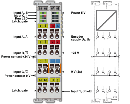
Figure 1: AKT2G-ENC-190-000
The AKT2G-ENC-190-000 EtherCAT Terminal is an interface for direct connection of incremental encoders with differential inputs (RS422). A 16-bit counter (in normal operating mode) or a switchable 16/32-bit counter (in enhanced operating mode) with a quadrature decoder and a 16-bit latch (in normal operating mode) or 32-bit latch (in enhanced operating mode) for the zero pulse can be read, set or enabled. Incremental encoders with alarm output can be connected at the negative switching status input of the interface. The measurement of period and frequency is possible. The gate input allows the locking of the counter, alternatively with a high or low level. The latch input is similarly configurable and evaluates high or low levels. The AKT2G-ENC-190-000 can also be used as bidirectional counter on channel A; channel B specifies the count direction.
Related Topics: Map Input and Output to Variables
Technology
The AKT2G-ENC-190-000 incremental encoder interface terminal enables connection of incremental encoders with
A/B/C track to the Bus Coupler and the PLC. A 16-bit counter (in normal operating mode) or a switchable 16/32-bit counter (in enhanced operating mode) with a quadrature decoder and a 16-bit latch (in normal operating mode) or 32-bit latch (in enhanced operating mode) can be read, set or enabled. Differential signals based on RS422 are provided as encoder connection. From hardware 09 single-ended 5 V signals are possible for the AKT2G-ENC-190-000 based on pull-up resistors.
In addition to the encoder inputs A, B and C, an additional latch input G1 (24 V) and a gate input G2 (24 V) for locking the counter during operation are available.
The terminal is supplied as a 4-fold quadrature decoder with complementary analysis of the sensor signals A, B, C. If the incremental encoder has an alarm output it can be connected to the INPUT 1 status input of the AKT2G-ENC-190-000. The AKT2G-ENC-190-000 can optionally be operated as a bidirectional counter terminal on channel A.
AKT2G-ENC-190-000 input impedance
The signal source must be able to operate the input impedance of the AKT2G-ENC-190-000 (typically 220 Ω, subject to modification) with adequate voltage levels according to RS422.
Gate/latch input
For gate and latch inputs (24 V) a max. input frequency of 1 MHz is permitted. Subject to modification.
Level on interface
In differential mode the AKT2G-ENC-190-000 expects the signal levels after RS422. The data are transferred without ground reference as voltage difference between two cables (signal A and inverted signal /A). The terminal analyses signal levels in the range -200 mV < Vid < +200 mV as valid signals. The differential signal must be in the common mode range (<+13.2 V and >-10 V, with respect to GND) (cf. diagram). Signal levels outside this range can lead to destruction.
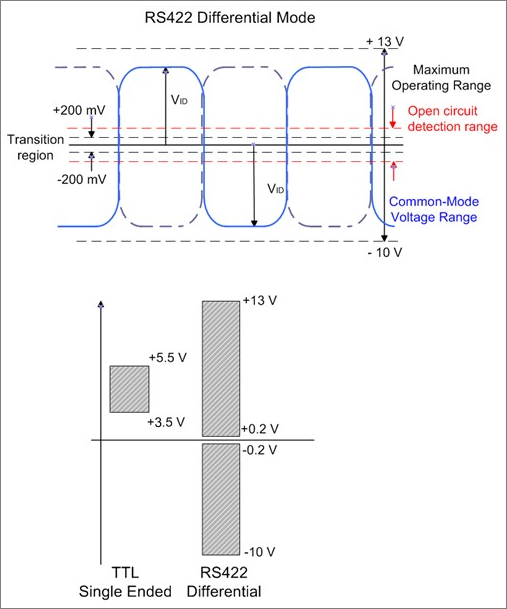
Figure 2: Level interface
In differential mode only the voltage difference is evaluated, so that common-mode interference on the transmission link does not lead to corruption of the wanted signal, since any interference affects both cables simultaneously.
If the AKT2G-ENC-190-000 is only operated in single-ended mode, a nominal level voltage between 3.5 V and 5.5 V is expected.
Technical Data
|
Technical Data |
AKT2G-ENC-190-000 |
|---|---|
| Sensor connection | A, ¬A, B, ¬B, C, ¬C (RS422 differential inputs) also single-ended connection (5 V ±20%) possible |
| Additional inputs |
gate, latch (24 VDC, both max. 1 MHz permitted), status input (max. 5 VDC, potential-free, switching to negative potential) |
| Encoder operating voltage / Encoder supply | 5 VDC (generated from the 24 V DC power contacts) |
| Sensor output current | 0.5 A |
| Counter | 16 bit, 16/32 bit switchable |
| Zero pulse latch | 16 bit, 16/32 bit switchable |
| Limit frequency | 1 MHz (equals 4 million increments with 4-fold evaluation) |
| Quadrature decoder | 4-fold evaluation |
| Distributed Clocks | in enhanced operating mode |
| Broken wire detection to sensor | in enhanced operating mode |
| Commands | read, set, enable |
| Cycle time | min. 100 µs |
| Current consumption via Ebus | typ. 130 mA |
| Current consumption from the power contacts | 0.1 A (excluding sensor load current) |
| Electrical isolation | 500 V (E-bus/field voltage) |
| Bit width in process image | up to 6 bytes outputs, 22 bytes inputs, depends on parametrization |
| MTBF (+55°C) | - |
| Weight | approx. 100 g |
| Permissible ambient temperature range during operation | -25°C ... +60°C (extended temperature range) |
| Permissible ambient temperature range during storage | -40°C ... +85°C |
| Permissible relative humidity | 95%, no condensation |
| Dimensions (W x H x D) | approx. 27 mm x 10 mm x 70 mm (width aligned: 24 mm) |
| Mounting | on 35 mm mounting rail conforms to EN 60715 |
| Vibration/shock resistance | conforms to EN 60068-2-6 / EN 60068-2-27, see also installation instructions for enhanced mechanical load capacity |
| EMC immunity/emission | conforms to EN 61000-6-2 / EN 61000-6-4 |
| Protection class | IP20 |
| Installation position | variable |
| Approval | CE ATEX cULus |


