AKT2G-PSF-024-000
Power Supply Terminal with fuse, 24 V DC
The AKT2G-PSF-024 feed terminal can be positioned at any location between the input and output terminals for establishing a further potential group or for supplying the terminals following on the right in applications with high current load. The E-Bus is looped through.
See Also:
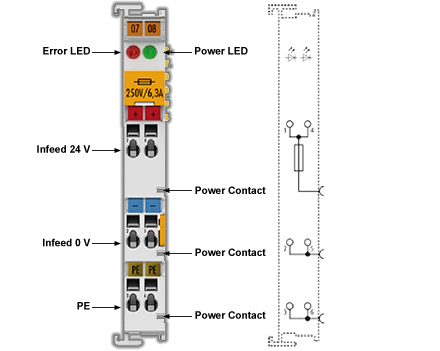
Connections
| Terminal Point | Description | |
|---|---|---|
| Indication | Number | |
| +24 V | 1 | Supply input + 24 V (connected internally with terminal 4 and positive power contact) |
| 0 V | 2 | 0 V for supply input (connected internally with terminal 5 and negative power contact) |
| PE | 3 | PE (connected internally with terminal 6 and PE power contact) |
| +24 V | 4 | Supply input + 24 V (connected internally with terminal 1 and positive power contact) |
| 0 V | 5 | 0 V for supply input (connected internally with terminal 2 and negative power contact) |
| PE | 6 | PE (connected internally with terminal 3 and PE power contact) |
LEDs
| LED | Color | Meaning | |
|---|---|---|---|
| Power LED | green | off | No input voltage at supply input |
| on | 24 VDC at supply input | ||
| Error LED | red | off | Fuse OK |
| on | Fuse error | ||
Technical Data
|
Technical Data |
AKT2G-PSF-024-000 |
|---|---|
| Nominal voltage | 24 VDC |
| Power contact current load | max. 10 A |
| Electrical isolation | 500 V (E-bus/field potential) |
| Integrated fine-wire fuse | yes; 6.3 A |
| Current consumption from E-Bus | - |
| Bit width in the process image | - |
| Configuration | no address or configuration settings |
| Power LED | yes |
| Diagnosis (fuse) | yes, Error LED |
| Electrical connection to mounting rail | no |
| PE contact | yes |
| Renewed infeed | yes |
| Connection facility to additional power contact | 1 |
| Side by side mounting on Bus Terminals with power contact | yes |
| Side by side mounting on Bus Terminals without power contact | yes |
| Weight | approx. 55 g |
| Permissible ambient temperature range (during operation) | 0°C ... +55°C |
| Permissible ambient temperature range (during storage) | -25°C ... +85°C |
| Permissible relative humidity | 95%, no condensation |
| Dimensions (W x H x D) | approx. 15mm x 100mm x 70mm (width aligned: 12mm) |
| Mounting | on 35mm mounting rail conforms to EN 60715 |
| Vibration/shock resistance | conforms to EN 60068-2-6/EN 60068-2-27 |
| EMC resistance burst/ESD | conforms to EN 61000-6-2/EN 61000-6-4 |
| Protection class | IP 20 |
| Installation position | variable, see Positioning of Passive Terminals |
| Approval | CE, ATEX, cULus |
-
-
Hazard to individuals and devices!
When designing a Bus Terminal block with different potentials on the power contacts (e.g., 230 V AC and 24 V DC), please note that it is mandatory to use potential separation terminals!
Bring the bus system into a safe, powered down state before starting installation, disassembly, or wiring of the Bus Terminals!