Notices on Analog Specifications
Kollmorgen I/O devices with analog inputs are characterized by a number of technical characteristic data; refer to the technical data in the respective sections. Some explanations are given below for the correct interpretation of these characteristic data.
Jump to a section on this page:
Measuring Error / Measurement Deviation
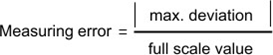
The relative measuring error (% of the full scale value) is referenced to the full scale value and is calculated as the quotient of the largest numerical deviation from the true value (‘measuring error’) referenced to the full scale value.
The measuring error is generally valid for the entire permitted operating temperature range, also called the ‘usage error limit’ and contains random and systematic portions of the referred device (i.e. ‘all’ influences such as temperature, inherent noise, aging, etc.).
It is always to be regarded as a positive/negative span with ±, even if it is specified without ± in some cases.
The maximum deviation can also be specified directly.
Example: Measuring range 0...10 V and measuring error < ± 0.3 % full scale value → maximum deviation ± 30 mV in the permissible operating temperature range.
-
-
Lower measuring error
Since this specification also includes the temperature drift, a significantly lower measuring error can usually be assumed in case of a constant ambient temperature of the device and thermal stabilization after a user calibration.
This applies to analog output devices.
Temperature Coefficient tK [ppm/K]
An electronic circuit is usually temperature dependent to a greater or lesser degree. In analog measurement technology this means that when a measured value is determined by means of an electronic circuit, its deviation from the "true" value is reproducibly dependent on the ambient/operating temperature.
A manufacturer can alleviate this by using components of a higher quality or by software means.
The temperature coefficient, when indicated, allows the user to calculate the expected measuring error outside the basic accuracy at 23 °C.
Due to the extensive uncertainty considerations that are incorporated in the determination of the basic accuracy (at 23 °C), Kollmorgen recommends a quadratic summation.
Example: Let the basic accuracy at 23 °C be ±0.01% typ. (full scale value), tK = 20 ppm/K typ.; the accuracy A35 at 35 °C is wanted, hence ΔT = 12 K

Remarks: ppm ≙ 10-6 % ≙ 10-2
Single-Ended / Differential Typification
For analog inputs Kollmorgen makes a basic distinction between two types: single-ended (SE) and differential (DIFF), referring to the difference in electrical connection with regard to the potential difference.
The diagram shows two-channel versions of an SE module and a DIFF module as examples for all multi- channel versions.
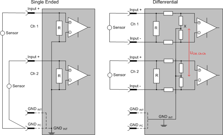
Figure 1: SE and DIFF module as 2-channel version
-
- Dashed lines indicate that the respective connection may not necessarily be present in each SE or DIFF module. Electrical isolated channels are operating as differential type in general, hence there is no direct relation (voltaic) to ground within the module established at all. Indeed, specified information to recommended and maximum voltage levels have to be taken into account.
The basic rule:
- Analog measurements always take the form of voltage measurements between two potential points. For voltage measurements a large R is used, in order to ensure a high impedance. For current measurements a small R is used as shunt. If the purpose is resistance measurement, corresponding considerations are applied.
- Kollmorgen generally refers to these two points as input+/signal potential and input-/reference potential.
- For measurements between two potential points two potentials have to be supplied.
- Regarding the terms "single-wire connection" or "three-wire connection", please note the following for pure analog measurements: three- or four-wire connections can be used for sensor supply, but are not involved in the actual analog measurement, which always takes place between two potentials/wires.
In particular this also applies to SE, even though the term suggest that only one wire is required.
- The term "electrical isolation" should be clarified in advance.
IO modules feature 1..8 or more analog channels; with regard to the channel connection a distinction is made in terms of:
- how the channels WITHIN a module relate to each other, or
- how the channels of SEVERAL modules relate to each other.
- The property of electrical isolation indicates whether the channels are directly connected to each other.
- Terminals (and related product groups) always feature electrical isolation between the field/analog side and the bus/EtherCAT side. In other words, if two analog terminals/ boxes are not connected via the power contacts (cable), the modules are effectively electrically isolated.
- If channels within a module are electrically isolated, or if a single-channel module has no power contacts, the channels are effectively always differential. See also explanatory notes below. Differential channels are not necessarily electrically isolated.
- Analog measuring channels are subject to technical limits, both in terms of the recommended operating range (continuous operation) and the destruction limit. Please refer to the respective terminal/ box documentation for further details.
Explanation
- differential (DIFF)
- Differential measurement is the most flexible concept. The user can freely choose both connection points, input+/signal potential and input-/reference potential, within the framework of the technical specification.
- A differential channel can also be operated as SE, if the reference potential of several sensors is linked. This interconnection may take place via the system GND.
- Since a differential channel is configured symmetrically internally (see Figure 1: "SE and DIFF module as 2-channel version"), there will be a mid-potential (X) between the two supplied potentials that is the same as the internal ground/reference ground for this channel. If several DIFF channels are used in a module without electrical isolation, the technical property VCM (common-mode voltage) indicates the degree to which the mean voltage of the channels may differ.
- The internal reference ground may be accessible as connection point at the terminal/ box, in order to stabilize a defined GND potential in the terminal/ box. In this case it is particularly important to pay attention to the quality of this potential (noiselessness, voltage stability). At this GND point a wire may be connected to make sure that VCM,max is not exceeded in the differential sensor cable. If differential channels are not electrically isolated, usually only one VCM, max is permitted. If the channels are electrically isolated this limit should not apply, and the channels voltages may differ up to the specified separation limit.
- Differential measurement in combination with correct sensor wiring has the special advantage that any interference affecting the sensor cable (ideally the feed and return line are arranged side by side, so that interference signals have the same effect on both wires) has very little effect on the measurement, since the potential of both lines varies jointly (hence the term common mode). In simple terms: Common-mode interference has the same effect on both wires in terms of amplitude and phasing.
- Nevertheless, the suppression of common-mode interference within a channel or between channels is subject to technical limits, which are specified in the technical data.
- Single Ended (SE)
- If the analog circuit is designed as SE, the input/reference wire is internally fixed to a certain potential that cannot be changed. This potential must be accessible from outside on at least one point for connecting the reference potential, e.g. via the power contacts (cable).
- In other words, in situations with several channels SE offers users the option to avoid returning at least one of the two sensor cables to the terminal/ box (in contrast to DIFF). Instead, the reference wire can be consolidated at the sensors, e.g. in the system GND.
- A disadvantage of this approach is that the separate feed and return line can result in voltage/ current variations, which a SE channel may no longer be able to handle. See common-mode interference. A VCM effect cannot occur since the module channels are internally always "hard- wired" through the input/reference potential.
Typification of the 2/3/4-wire connection of current sensors
Current transducers/sensors/field devices (referred to in the following simply as ‘sensor’) with the industrial 0/4-20 mA interface typically have internal transformation electronics for the physical measured variable (temperature, current, etc.) at the current control output. These internal electronics must be supplied with energy (voltage, current). The type of cable for this supply thus separates the sensors into Self-supplied sensors or Externally Supplied Sensors:
Self-supplied sensors
- The sensor draws the energy for its own operation via the sensor/signal cable + and -.
So that enough energy is always available for the sensor’s own operation and open-circuit detection is possible, a lower limit of 4 mA has been specified for the 4-20 mA interface; i.e. the sensor allows a minimum current of 4 mA and a maximum current of 20 mA to pass.
- 2-wire connection see Fig. 2-wire connection, cf. IEC60381-1
- Such current transducers generally represent a current sink and thus like to sit between + and – as a ‘variable load’. Refer also to the sensor manufacturer’s information.
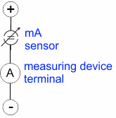
Figure 2: 2-wire connection
Therefore, they are to be connected according to the Kollmorgen terminology as follows:
- preferably to "single-ended" inputs if the +Supply connections of the terminal/ box are also to be used - connect to +Supply and Signal
- they can, however, also be connected to differential inputs, if the termination to GND is then manufactured on the application side – to be connected with the right polarity to +Signal and –Signal
Externally Supplied Sensors
- 3- and 4-wire connection see Figure 3: "Connection of externally supplied sensors", cf. IEC60381-1
- the sensor draws the energy/operating voltage for its own operation from 2 supply cables of its own. One or two further sensor cables are used for the signal transmission of the current loop:
- 1 sensor cable: according to the Kollmorgen terminology such sensors are to be connected to "single-ended" inputs in 3 cables with +/-/Signal lines and if necessary FE/shield
- 2 sensor cables: for sensors with 4-wire connection based on +supply/-supply/+signal/-signal, check whether +signal can be connected to +supply or –signal to –supply.
- Yes: then you can connect accordingly to a Kollmorgen "single-ended" input.
- No: the Kollmorgen "differential" input for +Signal and –Signal is to be selected; +Supply and – Supply are to be connected via additional cables.
-
-
Note: Expert organizations such as NAMUR demand a usable measuring range <4 mA/>20 mA for error detection and adjustment, see also NAMUR NE043.
The Kollmorgen device documentation must be consulted in order to see whether the respective device supports such an extended signal range.
Usually there is an internal diode existing within unipolar terminals/ boxes (and related product groups), in this case the polarity/direction of current have to be observed.
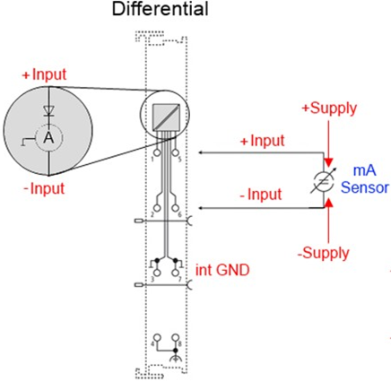
Figure 3: Connection of externally supplied sensors
Classification of the Kollmorgen terminals - Kollmorgen 0/4-20 mA terminals (and related product groups) are available as differential terminals (and related product groups):
| Differential |
|---|
| AN-240, AN-400: 0-20 mA |
| Preferred current direction because of internal diode |
| The terminal is a passive differential current measuring device; passive means that the sensor is not supplied with power. |
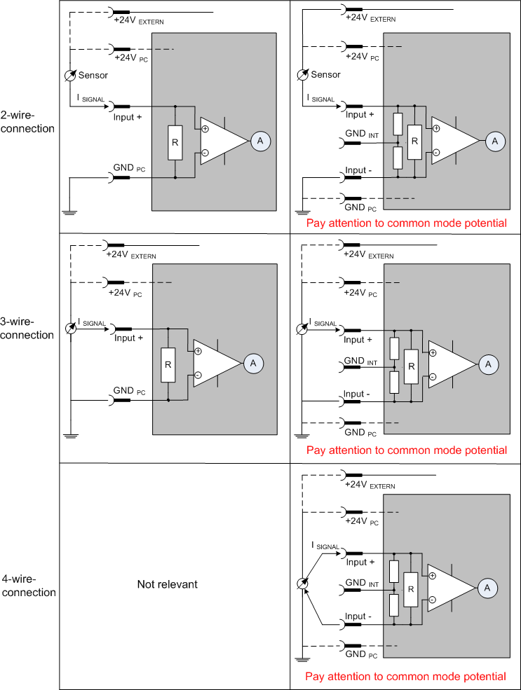
Figure 4: 2-, 3- and 4-wire connection at single-ended and differential inputs
Common-mode voltage and reference ground (based on differential inputs)
Common-mode voltage (Vcm) is defined as the average value of the voltages of the individual connections/ inputs and is measured/specified against reference ground.
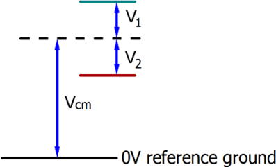
Figure 5: Common-mode voltage (Vcm)
The definition of the reference ground is important for the definition of the permitted common-mode voltage range and for measurement of the common-mode rejection ratio (CMRR) for differential inputs.
The reference ground is also the potential against which the input resistance and the input impedance for single-ended inputs or the common-mode resistance and the common-mode impedance for differential inputs is measured.
The reference ground is usually accessible at or near the terminal/ box, e.g. at the terminal contacts, power contacts (cable) or a mounting rail. Please refer to the documentation regarding positioning. The reference ground should be specified for the device under consideration.
For multi-channel terminals/ boxes with resistive (=direct, ohmic, galvanic) or capacitive connection between the channels, the reference ground should preferably be the symmetry point of all channels, taking into account the connection resistances.
Reference ground samples for Kollmorgen IO devices:
- Earth or SGND (shield GND):
- AKT2G-AN-400: No internal ground fed out to the terminal points, although capacitive coupling to SGND
Dielectric strength
A distinction should be made between:
- • Dielectric strength (destruction limit): Exceedance can result in irreversible changes to the electronics
- ◦ Against a specified reference ground
- ◦ Differential
- • Recommended operating voltage range: If the range is exceeded, it can no longer be assumed that the system operates as specified
- ◦ Against a specified reference ground
- ◦ Differential
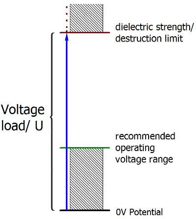
Figure 6: Recommended operating voltage range
The device documentation may contain particular specifications and timings, taking into account:
- Self-heating
- Rated voltage
- Insulating strength
- Edge steepness of the applied voltage or holding periods
- Normative environment (e.g. PELV)
Temporal Aspects of Analog/Digital Conversion
The conversion of the constant electrical input signal to a value-discrete digital and machine-readable form takes place in the analog Kollmorgen input modules with ADC (analog digital converter). Although different ADC technologies are in use, from a user perspective they all have a common characteristic: after the conversion a certain digital value is available in the controller for further processing. This digital value, the so-called analog process data, has a fixed temporal relationship with the “original parameter”, i.e. the electrical input value. Therefore, corresponding temporal characteristic data can be determined and specified for Kollmorgen analog input devices.
This process involves several functional components, which act more or less strongly in every AI (analog input) module:
- the electrical input circuit
- the analog/digital conversion
- the digital further processing
- the final provision of the process and diagnostic data for collection at the fieldbus (EtherCAT, K‑bus, etc.)
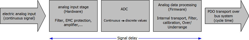
Figure 7: Signal processing analog input
Two aspects are crucial from a user perspective:
- “How often do I receive new values?”, i.e. a sampling rate in terms of speed with regard to the device/ channel
- What delay does the (whole) AD conversion of the device/channel cause?
I.e. the hardware and firmware components in its entirety. For technological reasons, the signal characteristics must be taken into account when determining this information: the run times through the system differ, depending on the signal frequency.
This is the “external” view of the “Kollmorgen AI channel” system – internally the signal delay in particular is composed of different components: hardware, amplifier, conversion itself, data transport and processing. Internally a higher sampling rate may be used (e.g. in the deltaSigma converters) than is offered “externally” from the user perspective. From a user perspective of the “Kollmorgen AI channel” component this is usually irrelevant or is specified accordingly, if it is relevant for the function.
For Kollmorgen AI devices the following specification parameters for the AI channel are available for the user from a temporal perspective:
- Minimum conversion time [ms, µs]
This is the reciprocal value of the maximum sampling rate [sps, samples per second]:
Indicates how often the analog channel makes a newly detected process data value available for collection by the fieldbus. Whether the fieldbus (EtherCAT, K-bus) fetches the value with the same speed (i.e. synchronous), or more quickly (if the AI channel operates in slow FreeRun mode) or more slowly (e.g. with oversampling), is then a question of the fieldbus setting and which modes the AI device supports.
For EtherCAT devices the so-called toggle bit indicates (by toggling) for the diagnostic PDOs when a newly determined analog value is available.
Accordingly, a maximum conversion time, i.e. a smallest sampling rate supported by the AI device, can be specified.
Corresponds to IEC 61131-2, section 7.10.2 2, “Sampling repeat time”
- Typical signal delay
Corresponds to IEC 61131-2, section 7.10.2 1, “Sampling duration”. From this perspective it includes all internal hardware and firmware components, but not “external” delay components from the fieldbus.
This delay is particularly relevant for absolute time considerations, if AI channels also provide a time stamp that corresponds to the amplitude value – which can be assumed to match the physically prevailing amplitude value at the time.
Due to the frequency-dependent signal delay time, a dedicated value can only be specified for a given signal. The value also depends on potentially variable filter settings of the channel.
A typical characterization in the device documentation may be:
- Signal delay (step response)
Keywords: Settling time
The square wave signal can be generated externally with a frequency generator (note impedance!) The 90 % limit is used as detection threshold.
The signal delay [ms, µs] is then the time interval between the (ideal) electrical square wave signal and the time at which the analog process value has reached the 90 % amplitude.
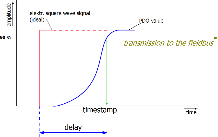
Figure 8: Diagram signal delay (step response)
- Signal delay (linear)
Keyword: Group delay
Describes the delay of a signal with constant frequency
A test signal can be generated externally with a frequency generator, e.g. as sawtooth or sine. A simultaneous square wave signal would be used as reference.
The signal delay [ms, µs] is then the interval between the applied electrical signal with a particular amplitude and the moment at which the analog process value reaches the same value.
A meaningful range must be selected for the test frequency, e.g. 1/20 of the maximum sampling rate.
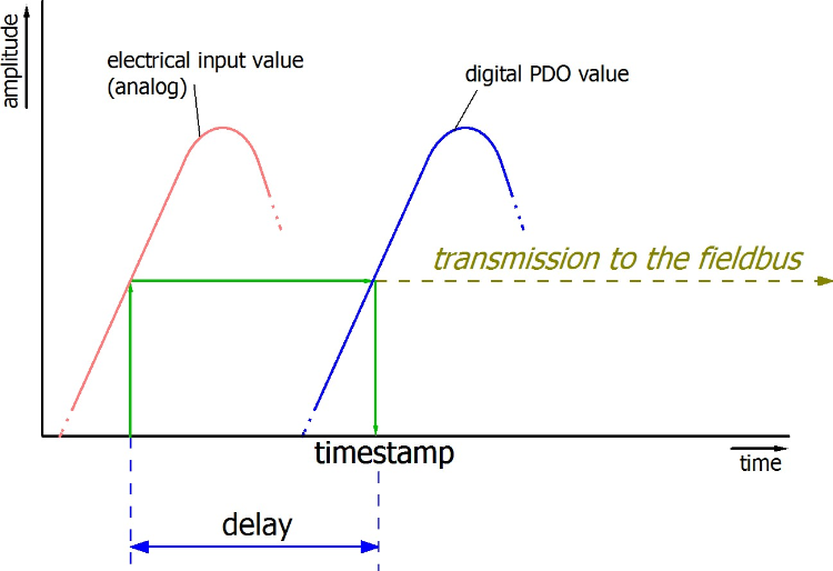
Figure 9: Diagram signal delay (linear)
- Additional Information
May be provided in the specification, e.g.
- Actual sampling rate of the ADC (if different from the channel sampling rate)
- Time correction values for run times with different filter settings
- etc.
- Signal delay (step response)