Unwind-Rewind Application Setup
User Units
Below is a summary of the user units used in the application. The virtual master, left winder and right winder have base units of degrees/sec. The draw roller and die cutter have base units of mm/sec. For the draw roller and die cutter the User Units (UU) per turn are calculated incorporating the diameters of the drive rollers. Note: DU = Drive Units
| Axis | Gear Ratio | DU per rev | UU per turn | Base Units | UU per (motor) rev | Axis Rollover |
|---|---|---|---|---|---|---|
|
1 Left Winder |
1 |
1048576 |
360 deg |
deg/sec |
DEF_A1_UUperTurn/DEF_A1_GearRatio = 360 |
360 |
|
2 Draw Roller |
10 |
1048576 |
202.24mm |
mm/sec |
DEF_A2_UUperTurn/DEF_A2_GearRatio = 202.24/10 = 20.2 |
150 |
|
3 Die Cutter |
1 |
1048576 |
300 mm |
mm/sec |
DEF_A3_UUperTurn/DEF_A3_GearRatio = 300/1 = 300 |
300 |
|
4 Right Winder |
1 |
1048576 |
360 deg |
deg/sec |
DEF_A4_UUperTurn/DEF_A4_GearRatio = 360/1 = 360 |
360 |
|
Virtual Master |
--- |
--- |
--- |
deg/sec |
360 |
360 |
Defines
Purpose
In the project tree the Defines section contains value for project parameters to configure the project for a particular machine mechanics and desired machine performance. With Defines, the KAS application program can be tailored for a variety of machine types.
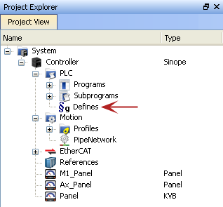
Defines can be used as compiler directives and set up the application for individual machine needs including for the following:
- Machine Mechanics
- M1 (Main) status masks – sets up bits in the Machine status word
- Ax (Axis) status masks – set up definition for bits in the Axis Status Words
- M1 (Main) initialization – virtual axis motion setup
- Machine states – sets up the machine states used in the application
- System timers
- IO mapping
Status Mask
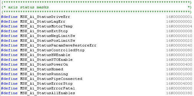
Status mask are used to setup the bit definitions of the Axis and Machine Status Words: A1_StatusWord, A2_StatusWord, and M1_StatusWord. Example: The bit masks for A1_StatusWord are:
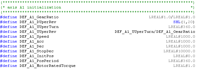
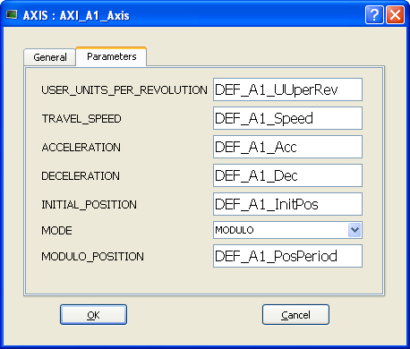
Initial parameters in Pipe Network Blocks
These parameters are used to initialize the motion parameters in the pipe network block. Example: several of the following parameters are used to define the AX1_A1_Axis Pipe network block:

Machine States and Timers
Defines are used to define Machine States and Timer values

Load and Save Drive Parameters
Defines are used to help setup an array to read and write AKD drive parameters:


See Appendix for a full listing of defines
Ethercat Setup
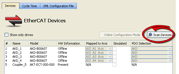
Scanning
The system’s Ethercat network can be configured into the project by using the ‘Scan Devices’ feature once the controller has been connected to the items (drives and remote I/O) on the network.
Drive Setup
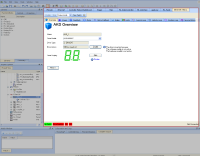
The commissioning of each drive can be accomplished by opening the AKD item. Once this is open each drive can be configured for line voltage, the motor and load including tuning, system limitations and the parameters. The available screens embedded in the KAS IDE are similar, although not all the same, as the AKD GUI View screens.
IO Setup
IO points can be set up in the project using the KAS IO support screens in the Ethercat section of the Project file
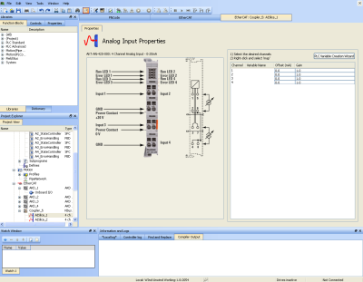
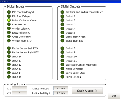
The value of the IO is displayed in the following Kollmorgen AKI screen:
