 to add the Fieldbus configuration
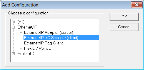
The KAS RuntimeIn computer science, runtime (or run-time) describes the operation of a computer program, the duration of its execution, from beginning to termination (compare compile time). Within KAS, runtime also refers to the virtual machine that manage the program written in a computer language while it is running includes a fully integrated EthernetEthernet is a large, diverse family of frame-based computer networking technologies that operate at many speeds for local area networks (LANs)/IP client driver for exchanging CIP"Common Industrial Protocol " The Common Industrial Protocol allows complete integration of control with information, multiple CIP Networks, and Internet technologies I/O assemblies as an Ethernet/IP scanner in your applications.
Data Exchange - Configuration
A dedicated configuration tool is integrated in the KAS IDE"Integrated development environment" An integrated development environment is a type of computer software that assists computer programmers in developing software. IDEs normally consist of a source code editor, a compiler and/or interpreter, build-automation tools, and a debugger.
to add the Fieldbus configuration The configuration is represented as a tree:
(*) The items with this mark can appear several times in the configuration.
Configuration of the Server
Click the Insert Master icon  to declare a server (slave adapter). Each server is identified by its IP address and an optional Description text.
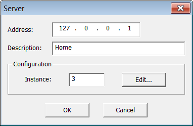
Three blocks of data are exchanged with the server for each connection:
The instance number for the configuration may be specified in the properties of the server.
Editing the Configuration Data Block
While most devices do not expect any configuration it may happen that some data is required. For this, double click on the server in the tree and press the Edit... button in the dialog box.
The configuration is entered as a list of items. Use the Type button to specify the number of items and their data types. Structured data types defined in the KAS IDE are supported. Simply enter values in the grid. In case you exchange multiple byte integers (e.g. WORD) you must specify whether the device expects little or big endian formatting.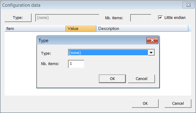
Configuring an Assembly
Click the Insert Slave icon  to declare a CIP I/O assembly. Each assembly is identified by:
| Identifier | Meaning |
|---|---|
| Type | Direction of the I/O assembly. Can be one of:
|
| Instance | Instance of the CIP assembly |
| Config.instance | The instance number of the configuration assembly. The default value is 100. 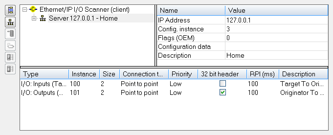 |
| Size | Data size in bytes |
| Connection type | Type of the CIP connection. Can be Point To Point or MultiCast |
| Priority | CIP priority: Low, High, Scheduled or Urgent |
| 32 bit header | Check this option if a 32 bit header is to be sent on notifications |
| RPI(ms) | Minimum period for notification of changes, in milliseconds (range is 10 - 10000 ms) |
| Description | Optional description text |
Configuring Variables
IEC61131-3IEC 61131-3 is the third part of the open international standard IEC 61131. The current (second) edition was published in 2003. IEC 61131-3 currently defines five programming languages for programmable control systems It deals with programming languages and defines two graphical and two textual PLC programming language standards variables may be mapped on the data of the assembly. For each variable you must specify:
| Identifier | Meaning |
|---|---|
| Symbol | The name of the IEC61131IEC standard for Programmable logic controllers (PLCs)-3 variable |
| Offset | Offset in bytes in the assembly data |
| Bit | Bit offset in the selected byte if format is "Bit" |
| Format | Format of the data in the assembly |
| Mode | Kind of data exchanged through the variable:
|
The data limit is: 500 bytes of data maximum O(originator)->T(target) and 500 bytes of data maximum T(target) -> O(originator). This is based on the Ethernet/IP specification.
|
Stay Connected with Kollmorgen       
|
Copyright © 2015 Kollmorgen™ |

|