The configuration is represented as a tree:
- Profinet IO Configuration
- Profinet IO device (*)
- Group (*)
- Variable (*)
- Group (*)
(*) These items can appear several times in the configuration (depending on the bus topology).
- Profinet IO device (*)
The I/Os of the Profinet network must be connected to the variables via a Profinet IO device.
These parameters can be changed:
| Parameter | Meaning |
|---|---|
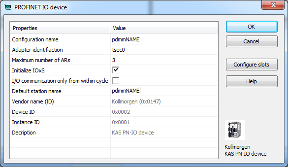
| Name | A device name can consists of labels and must follow these conventions:
|
| Adapter identification | Must be “tsec0” |
| Maximum # of ARs | Maximum number of alarm retries (default 3). |
| Initialize IOxS | On: Initialize IOxS with good status.
Off: No initialization of IOxS.
|
| IO communication only from within cycle | On: Run IO communication from within VM-cycle
Off: Run IO communication outside VM-cycle.
|
| Default station name | Name of the station. |
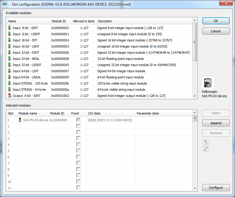
You can not configure each module. Only modules with some sub modules respectively with a sub module with parameter data can be configured. Mark the according module in the lower list and click the Configure button.
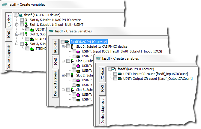
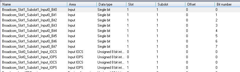
Every Profinet variable is expanded to a set of Boolean variables in PLC"Programmable Logic Controller" A Programmable Logic Controller, PLC, or Programmable Controller is a digital computer used for automation of industrial processes, such as control of machinery on factory assembly lines. Used to synchronize the flow of inputs from (physical) sensors and events with the flow of outputs to actuators and events by default. A SINT slot, for example, will be mapped to eight PLC BOOL variables. Therefore, if you have many configured slots, many PLC variables will be produced. The PDMM or PCMM will be slowed by a large amount of PLC variables.
To avoid this, you can right click on a slot in the Create variables dialog and select Pack bits. Doing so with a SINT slot, for example, will create one SINT variable in KAS instead of eight BOOL variables. This will help reduce the number of PLC variables and reduce the load on the PDMM or PCMM.
The Pack bits action may be applied to all slots by right clicking on the root node in the Create variables dialog.
These parameters can be changed:
| Parameter | Meaning |
|---|---|
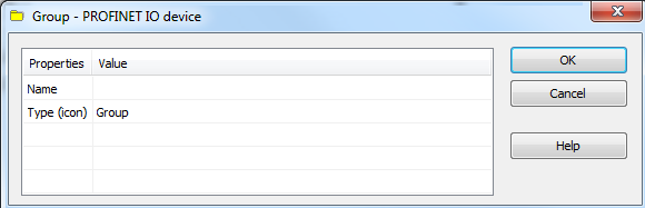
| Name | Name of the group |
| Type (icon) | Icon used for the group |
These parameters can be changed:
| Parameter | Description |
|---|---|
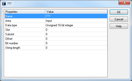
| Variable name | Variable name following the IEC"International Electrotechnical Commission" IEC is a not-for-profit, non-governmental international standards organization that prepares and publishes International Standards for all electrical, electronic and related technologies 61131-3 syntax. |
| Area | Output, Output IOCS, Output IOPS, Input, Input IOCS, Input IOPS, device status. |
| Format | 32 bit float, Signed 16 bit integer, Signed 32 bit integer, Signed 8 bit integer, Single bit, Unsigned 16 bit integer, Unsigned 32 bit integer, Unsigned 8 bit integer. |
| Slot | Slot Number |
| Subslot | Subslot Number |
| Offset | Offset |
| Bit | Bit |
The offset of a variable is relative to a sub module. Thus also depending from a slot and subslot. The offset of the first variable of a sub module is always 0.